How to Use INA219 Current Sensor for Real-Time Power Monitoring on ESP32
Using the INA219 Current Sensor for Real-Time Power Monitoring on ESP32 Boards
If you've ever wondered how much power your project actually draws—not just what the datasheet says—the INA219 is your answer. It's a high-side current/voltage sensor that communicates over I2C, and it gives you bus voltage, current, and power readings without needing to break your ground path or do any math yourself. The chip handles the shunt voltage measurement and current calculation internally.
Pairing it with an ESP32 and the Arduino framework gives you a quick real-time power monitor you can use to profile your circuits, validate sleep mode current, or just sanity-check your power budget.
Prerequisites
- Basic electronics knowledge (what current, voltage, and I2C are)
- Arduino programming experience
- Arduino IDE 2.x with ESP32 board support (Arduino ESP32 core v3.x)
Parts/Tools
- 1 x ESP32 Development Board
- 1 x INA219 Current Sensor Module (breakout board)
- Jumper Wires
- Breadboard
- The load circuit you want to measure
Steps
- Wiring the INA219 to the ESP32
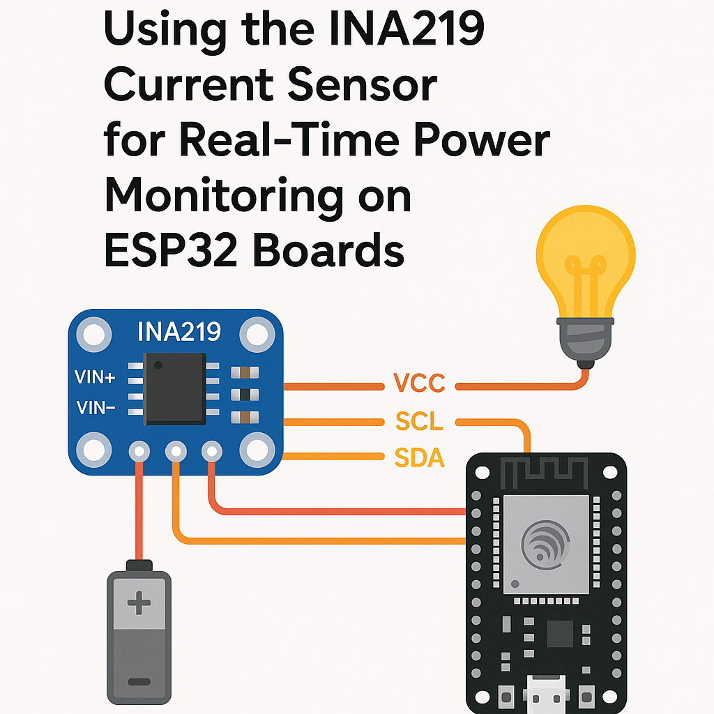
- Connect the INA219 breakout to the ESP32:
- The INA219 is a high-side sensor. That means it goes in series with the positive supply line of whatever you're measuring. Connect your supply's positive wire to VIN+ on the INA219, and VIN- goes to your load's positive input. The load's ground connects back to the supply's ground as normal.
- Watch out: if you wire it on the low side (in the ground path), you'll still get readings, but they won't be accurate because the INA219's internal reference assumes high-side placement. The common-mode voltage range matters here.
INA219 ESP32 VCC 3.3V GND GND SDA GPIO 21 SCL GPIO 22 - Installing the Required Library
- Open Arduino IDE 2.x.
- Go to the Library Manager (left sidebar icon or Tools > Manage Libraries).
- Search for Adafruit INA219 and install it. It'll pull in the Adafruit BusIO dependency automatically.
- Make sure you're on Arduino ESP32 core v3.x. Older core versions can have I2C timing issues with certain sensor libraries.
- Writing the Code
- Create a new sketch and add the includes:
- Create the sensor object. The default I2C address is 0x40. If you've bridged the address jumpers on the breakout board, pass the correct address here:
- Set up initialization with proper error handling:
- Read and display the measurements in your loop:
#include <Wire.h> #include <Adafruit_INA219.h>Adafruit_INA219 ina219; // defaults to 0x40 // Adafruit_INA219 ina219(0x41); // if A0 jumper is bridgedvoid setup() { Serial.begin(115200); while (!Serial) { delay(10); } if (!ina219.begin()) { Serial.println("INA219 not found. Check wiring."); while (1) { delay(10); } } Serial.println("INA219 ready."); // Optional: for measuring smaller currents with more precision // ina219.setCalibration_16V_400mA(); }Tip: the default calibration is 32V/2A. If your load draws less than 400mA, calling
setCalibration_16V_400mA()gives you much better resolution. There's also a 32V/1A option. Pick the range closest to your actual usage.void loop() { float busVoltage = ina219.getBusVoltage_V(); float current_mA = ina219.getCurrent_mA(); float power_mW = ina219.getPower_mW(); float shuntVoltage = ina219.getShuntVoltage_mV(); // The actual load voltage = bus voltage + shunt voltage drop float loadVoltage = busVoltage + (shuntVoltage / 1000.0); Serial.printf("Load: %.2fV %.2fmA %.2fmW\n", loadVoltage, current_mA, power_mW); delay(1000); }A subtlety most tutorials skip:
getBusVoltage_V()measures the voltage at VIN-, not VIN+. The actual voltage across your load is the bus voltage plus the shunt voltage drop. For low-current loads the difference is negligible, but at higher currents that shunt drop matters. - Uploading the Code
- Connect your ESP32 via USB.
- In Arduino IDE 2.x, select your board from Tools > Board > esp32 (pick your specific variant).
- Select the correct port under Tools > Port.
- Hit Upload. If the upload fails, hold the BOOT button on the ESP32 during the "Connecting..." phase.
- Testing the Setup
- Open the Serial Monitor (115200 baud).
- You should see voltage, current, and power readings printing every second.
- Try connecting different loads to VIN+/VIN- and watch the values change. An LED with a resistor is an easy first test—you should see 10–20mA depending on the resistor value.
- If readings show 0mA current, you probably don't have anything connected between VIN+ and VIN-. The sensor only measures current flowing through its shunt resistor.
Troubleshooting
- "INA219 not found" on startup: Run an I2C scanner sketch to verify the sensor is responding. Check SDA/SCL connections and make sure you haven't accidentally swapped them. Also confirm VCC is connected—the INA219 won't respond on I2C without power (obvious, but it happens).
- Readings are stuck at zero: The INA219 is working, but no current is flowing through the shunt. Make sure your load is connected between VIN+ and VIN-, and that the load circuit is actually powered and drawing current.
- Negative current values: You've got VIN+ and VIN- swapped. Reverse the connections on those two pins.
- Readings seem inaccurate: Check which calibration mode you're using. The default 32V/2A range has limited resolution for small currents. Switch to
setCalibration_16V_400mA()for loads under 400mA. Also, avoid running long wires to the sensor—resistance in the wiring adds to the shunt resistance and throws off the calculation.
Conclusion
You've got a working real-time power monitor using the INA219 and ESP32. This is a tool you'll reach for constantly once you have it set up—profiling sleep modes, comparing regulator efficiency, catching unexpected current spikes. Next steps could include logging data to an SD card or sending it over Wi-Fi to a dashboard, adding multiple INA219 sensors on different I2C addresses to monitor several supply rails simultaneously, or integrating it into a battery-powered project to track energy consumption over time.