How to Use ESP32 for I2S Audio Playback and Recording with DAC and Mic
Introduction
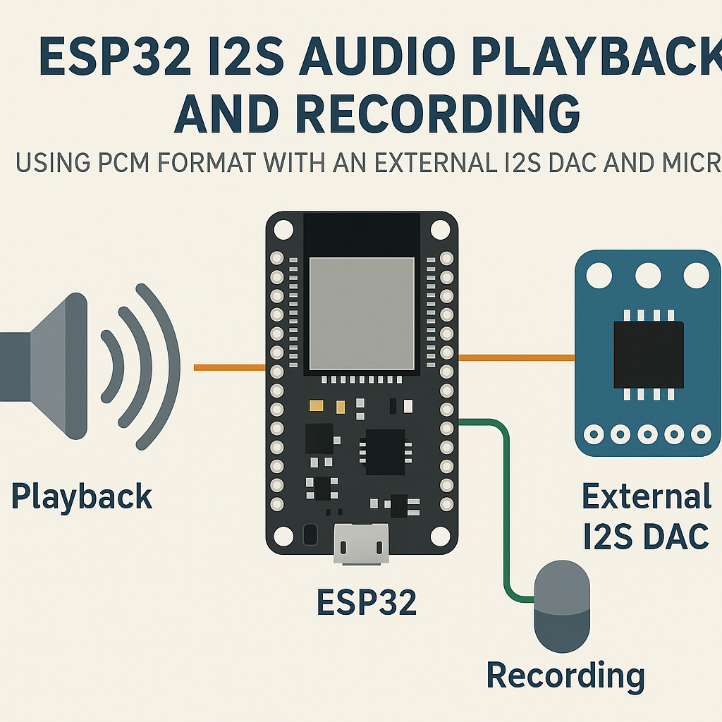
The ESP32 has a built-in I2S (Inter-IC Sound) peripheral, which means you can do real audio work—playback through an external DAC and recording from a digital microphone—without any extra audio codec ICs or complex analog circuitry. I2S handles the clocking and data transfer for you at the hardware level, so your code just shuffles PCM buffers around.
This guide walks you through wiring up a PCM5102 DAC for output and an INMP441 MEMS mic for input, then writing the code to drive both using the ESP-IDF I2S driver on Arduino ESP32 core v3.x.
Prerequisites
- Familiarity with Arduino IDE 2.x and ESP32 programming basics.
- ESP32 development board (any variant with I2S support—most have it).
- External I2S DAC module (e.g., PCM5102 breakout).
- I2S MEMS microphone (e.g., INMP441).
- Jumper wires for hookup.
- Arduino IDE 2.x with ESP32 board support (Arduino ESP32 core v3.x) installed.
Parts/Tools
- ESP32 Development Board
- PCM5102 I2S DAC Module
- INMP441 I2S Microphone
- Jumper Wires
- Computer with Arduino IDE 2.x
Steps
- Wiring the Components
- Connect the I2S DAC to the ESP32:
Pin ESP32 | Pin DAC ----------------|-------- GPIO 25 (BCK) | BCK GPIO 26 (LRCK) | LRCK GPIO 27 (DATA) | DATA GND | GND VCC | VCC - Connect the I2S microphone to the ESP32:
Pin ESP32 | Pin Microphone -----------------|--------------- GPIO 22 (BCK) | BCK GPIO 23 (LRCK) | LRCK GPIO 21 (DATA) | DATA GND | GND VCC | VCC - Watch out: the INMP441's L/R select pin determines the channel. Tie it to GND for left channel or VCC for right. If you leave it floating, you'll get erratic behavior or silence on one channel.
- For the PCM5102, tie the SCK pin to GND—this tells it to generate its own system clock internally. Skip this and you'll get no output at all.
- Connect the I2S DAC to the ESP32:
- Setting Up the Arduino IDE
- Open Arduino IDE 2.x.
- Make sure you have the ESP32 board package (v3.x) installed via the Board Manager. The Arduino ESP32 core v3.x ships with the ESP-IDF I2S driver built in, so you don't need a separate I2S library.
- If you're on an older core version (v2.x), the I2S API is different. I'd recommend upgrading—the v3.x driver API is cleaner and maps more directly to ESP-IDF v5.3+.
- Writing the Code
- Create a new sketch and include the I2S driver header:
#include <driver/i2s_std.h>Note: The older
#include <driver/i2s.h>legacy driver still works in ESP-IDF v5.3 but is deprecated. The newi2s_std.hdriver is the way forward. - Configure the I2S channel for playback. Here's a minimal setup at 44.1 kHz, 16-bit stereo:
void setup() { Serial.begin(115200); i2s_chan_handle_t tx_handle; i2s_chan_config_t chan_cfg = I2S_CHANNEL_DEFAULT_CONFIG(I2S_NUM_0, I2S_ROLE_MASTER); i2s_new_channel(&chan_cfg, &tx_handle, NULL); i2s_std_config_t std_cfg = { .clk_cfg = I2S_STD_CLK_DEFAULT_CONFIG(44100), .slot_cfg = I2S_STD_PHILIPS_SLOT_DEFAULT_CONFIG(I2S_DATA_BIT_WIDTH_16BIT, I2S_SLOT_MODE_STEREO), .gpio_cfg = { .bclk = GPIO_NUM_25, .ws = GPIO_NUM_26, .dout = GPIO_NUM_27, .din = I2S_GPIO_UNUSED, }, }; i2s_channel_init_std_mode(tx_handle, &std_cfg); i2s_channel_enable(tx_handle); } - Implement audio playback by writing PCM data to the TX channel:
void playAudio(i2s_chan_handle_t tx_handle) {
    uint8_t audioData[512]; // Fill this with your PCM samples
    size_t bytes_written = 0;
    i2s_channel_write(tx_handle, audioData, sizeof(audioData), &bytes_written, portMAX_DELAY);
}
Tip: If you hear clicks or pops, your buffer is too small or you're not feeding data fast enough. Increase the DMA buffer count in the channel config to give yourself more breathing room.
- For recording, set up a second I2S channel (I2S_NUM_1) with the mic pins and read from it:
void recordAudio(i2s_chan_handle_t rx_handle) {
    uint8_t audioData[512];
    size_t bytes_read = 0;
    i2s_channel_read(rx_handle, audioData, sizeof(audioData), &bytes_read, portMAX_DELAY);
    // Process your captured PCM data here
}
- Create a new sketch and include the I2S driver header:
- Uploading the Code
- Connect the ESP32 to your computer via USB.
- Select your board (e.g., "ESP32 Dev Module") and the correct COM port in Arduino IDE 2.x.
- Click Upload. If the upload fails, hold the BOOT button on your ESP32 during the "Connecting..." phase.
- Testing the Setup
- Open the Serial Monitor at 115200 baud to check for any error messages from the I2S driver.
- For playback testing, feed a known sine wave buffer to the DAC and listen with headphones or a speaker. If you hear a clean tone, your wiring and config are good.
- For recording testing, read mic data and print the raw values to Serial. You should see values fluctuating around zero—if they're pinned at max or min, check your wiring.
Troubleshooting
- Issue: No sound from DAC
- Double-check that the PCM5102's SCK pin is tied to GND.
- Verify the DAC is getting clean 3.3V power. Some cheap breakout boards are picky about supply noise.
- Make sure you're sending valid PCM data—an all-zeros buffer means silence, which is technically working correctly.
- Check that the BCLK, WS (LRCK), and DATA pins match what's in your code.
- Issue: No audio recording or garbage data
- Confirm the INMP441 is powered at 3.3V (not 5V—it'll work but the output levels will be wrong).
- Verify the L/R select pin is tied to a known state, not floating.
- Use a logic analyzer or oscilloscope on the data line to confirm the mic is actually clocking out bits.
- Watch out: the INMP441 outputs 24-bit data in a 32-bit frame. If you configure for 16-bit, you'll get truncated samples. Set your slot width to 32-bit and bit-shift the result.
Conclusion
You now have a working I2S audio setup on the ESP32 with both playback (via PCM5102 DAC) and recording (via INMP441 mic). From here, you can layer on SD card WAV file playback, real-time audio processing, or even stream audio over Wi-Fi. The ESP32's dual I2S peripherals let you run input and output simultaneously on separate buses, which is exactly what you need for things like voice assistants or audio effects processors.