How to Tune a Digital PID Controller for Buck Converter with STM32F4
Digital PID Control for a Buck Converter on STM32F4
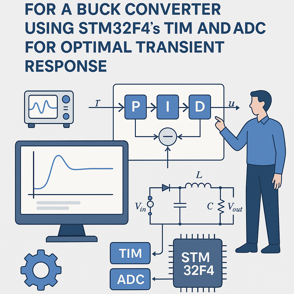
Your buck converter's output voltage is only as good as your control loop. Open-loop PWM is fine for an LED dimmer, but if you need a stable regulated voltage under varying loads, you need a closed-loop controller. The PID algorithm is the workhorse here — it's been around for over a century because it works. On an STM32F4, you've got hardware timers for precise PWM generation, a fast 12-bit ADC for voltage feedback, and a Cortex-M4 FPU for floating-point math without penalty. That's everything you need for a tight digital control loop.
This walkthrough focuses on getting the PID running and then actually tuning it so the transient response is usable — because a PID with bad gains is worse than no PID at all.
Prerequisites
- Understand what P, I, and D terms do individually (if "integral windup" doesn't ring a bell, brush up first)
- Comfortable writing C for STM32 using the HAL library
- STM32CubeIDE v1.16+ installed
- Know how a buck converter works at the circuit level
- Have an oscilloscope — you cannot tune a control loop by guessing
Parts/Tools
- STM32F4 development board (Nucleo-F446RE, Discovery, etc.)
- Buck converter circuit with accessible gate driver input and output voltage sense point
- Bench power supply for the converter input
- Oscilloscope (at least 2 channels — one for output voltage, one for PWM)
- Connecting wires
- Load resistor or electronic load for testing transient response
Steps
- Wire Up the Buck Converter
Connect the buck converter's gate driver input to the STM32F4's timer output pin. Run the converter's output through a resistor divider to bring it into the 0–3.3V range for the ADC. Double-check your divider math — feeding more than 3.3V into an STM32 ADC pin will damage it.
Connect your load (resistor or electronic load) to the converter output. Hook up the oscilloscope: Channel 1 on the output voltage, Channel 2 on the PWM signal.
- Configure TIM and ADC in CubeMX
Open STM32CubeIDE, create a new project for your F4 board, and configure the peripherals in the CubeMX view:
- Timer: Enable a timer (e.g., TIM1 for advanced-control timers with complementary outputs, or TIM2 for general purpose) in PWM Generation mode. Calculate your prescaler and ARR values for the desired switching frequency. For a 100kHz switching frequency on a 168MHz timer clock: prescaler = 0, ARR = 1679.
- ADC: Enable an ADC channel connected to your voltage feedback pin. Set the resolution to 12-bit. For best results, trigger the ADC conversion from the timer's update event — this synchronizes your sampling with the PWM cycle and avoids aliasing noise from the switching transients.
Generate the initialization code.
- Write the PID Control Algorithm
Here's a PID implementation with proper time scaling and anti-windup. The STM32F4's FPU handles the float math in single cycles, so there's no performance concern:
typedef struct {
    float Kp;
    float Ki;
    float Kd;
    float dt;           // Sample period in seconds
    float integral;
    float prev_error;
    float out_min;
    float out_max;
} PID_State;

void PID_Init(PID_State *pid, float kp, float ki, float kd, float dt,
              float out_min, float out_max) {
    pid->Kp = kp;
    pid->Ki = ki;
    pid->Kd = kd;
    pid->dt = dt;
    pid->integral = 0.0f;
    pid->prev_error = 0.0f;
    pid->out_min = out_min;
    pid->out_max = out_max;
}

float PID_Update(PID_State *pid, float setpoint, float measured) {
    float error = setpoint - measured;

    pid->integral += error * pid->dt;
    // Anti-windup: clamp integral term
    float i_term = pid->Ki * pid->integral;
    if (i_term > pid->out_max) {
        i_term = pid->out_max;
        pid->integral = pid->out_max / pid->Ki;
    } else if (i_term < pid->out_min) {
        i_term = pid->out_min;
        pid->integral = pid->out_min / pid->Ki;
    }

    float d_term = pid->Kd * (error - pid->prev_error) / pid->dt;
    pid->prev_error = error;

    float output = (pid->Kp * error) + i_term + d_term;

    // Clamp final output
    if (output > pid->out_max) output = pid->out_max;
    if (output < pid->out_min) output = pid->out_min;

    return output;
}
Using a struct makes it easy to have multiple PID instances if you ever need to control more than one converter, and it keeps state out of global variables.
- Implement the Main Loop
Read the ADC, run the PID, update the PWM compare register. For a first pass, polling is fine. Once it works, move the PID update into a timer interrupt for deterministic timing:
PID_State voltage_pid;

int main(void) {
    HAL_Init();
    SystemClock_Config();
    MX_TIM2_Init();
    MX_ADC1_Init();

    // 100kHz = 10us period, output range 0 to ARR
    PID_Init(&voltage_pid, 1.0f, 0.1f, 0.01f, 0.00001f, 0.0f, 1679.0f);
    HAL_TIM_PWM_Start(&htim2, TIM_CHANNEL_1);

    float setpoint = 5.0f; // Desired output voltage

    while (1) {
        HAL_ADC_Start(&hadc1);
        HAL_ADC_PollForConversion(&hadc1, HAL_MAX_DELAY);
        uint32_t raw = HAL_ADC_GetValue(&hadc1);
        // Convert ADC reading to voltage (adjust for your divider)
        float measured = (raw / 4096.0f) * 3.3f * 2.0f;

        float duty = PID_Update(&voltage_pid, setpoint, measured);
        __HAL_TIM_SET_COMPARE(&htim2, TIM_CHANNEL_1, (uint32_t)duty);
    }
}
That
* 2.0ffactor is for a 2:1 resistor divider. Change it to match your actual circuit. - Tune the PID Parameters
This is where the oscilloscope earns its keep. I typically use manual tuning for power converters since they're well-behaved enough that Ziegler-Nichols tends to be overly aggressive:
- Start P-only: Set Ki = 0, Kd = 0. Increase Kp from something small (0.1) until the output responds quickly to setpoint changes. If it starts oscillating, you've gone too far — note that value and back off to about 50-60% of it.
- Add I: Slowly increase Ki to eliminate the steady-state error (the gap between setpoint and actual output). Watch the step response on the scope. Too much Ki causes overshoot and a slow "ringing" oscillation. You want zero steady-state error with minimal overshoot.
- Add D: Kd reduces overshoot and speeds up settling. Start very small. The derivative term amplifies high-frequency noise from the ADC, so there's a practical limit. If the PWM output starts looking noisy/jittery, you've added too much Kd.
Test at multiple load points. A converter that's tuned at 50% load might oscillate at 10% load or have sluggish response at 100%. You need gains that work across your entire operating range. If you can't find a single set of gains that works everywhere, you might need gain scheduling or a different control topology.
Troubleshooting
- Output voltage not stable / oscillating:
Almost always a tuning issue. Reduce Kp first. If that doesn't help, check that your ADC conversion factor matches reality — measure the actual output with a multimeter and compare to what the code thinks the voltage is. A scaling error means the PID is chasing a phantom setpoint.
- ADC readings are garbage:
Verify the ADC pin configuration in CubeMX (analog mode, correct channel). Check your physical wiring. If readings are noisy, add a small capacitor (100nF) at the ADC input and consider averaging multiple samples. Also make sure nothing else is using that ADC pin as GPIO.
- PWM output isn't doing anything:
Did you call
HAL_TIM_PWM_Start()? This is the most common oversight. Also verify the timer output pin is correctly mapped in CubeMX — some pins have alternate function remapping, and the wrong AF selection means no output even though the timer is running internally. - Massive overshoot on startup:
Your integral term is winding up during the ramp from 0V to setpoint. Make sure anti-windup is implemented and the clamp values are reasonable. You can also add soft-start logic that gradually increases the setpoint from 0 to the target over a few hundred milliseconds.
Going Further
Once the basic loop works, the biggest improvement is moving the PID calculation into a timer interrupt so it executes at a fixed, deterministic rate. Polling in the main loop means your control bandwidth depends on whatever else the CPU is doing. For a production design, you'd also want input voltage feedforward (to reject supply variations before they hit the output), overcurrent protection, and possibly a switch to fixed-point math if you're targeting an M0/M3 core without an FPU. On the STM32F4's Cortex-M4F, float performance is excellent, so stick with floats unless you have a specific reason not to.