How to Scan I2C Bus and Retrieve MPU6050 Data with STM32 HAL Library
Introduction
The MPU6050 is one of the most popular accelerometer/gyroscope combo modules in the hobby and prototyping world, and for good reason—it's cheap, well-documented, and talks I2C. Before you start reading motion data, though, you need to make sure your STM32 can actually see the device on the bus.
This guide covers two things: writing an I2C bus scanner to detect connected devices, and then reading accelerometer data from the MPU6050 using the STM32 HAL library. I2C bus scanning is a useful debugging technique you'll reach for over and over, not just with the MPU6050.
Prerequisites
- Basic STM32 development experience (you've built and flashed at least one project)
- STM32 development board (F4, F1, L4—any series with I2C will work)
- MPU6050 breakout module
- ST-Link programmer (usually built into Nucleo/Discovery boards)
- STM32CubeIDE v1.16+ installed
- Jumper wires and a breadboard
Parts/Tools
- STM32 development board
- MPU6050 module
- Jumper wires
- ST-Link programmer (or onboard debugger)
- STM32CubeIDE v1.16+
Steps
- Set up your STM32 project
- Open STM32CubeIDE and create a new STM32 project. Select your board or MCU from the target selector.
- In the CubeMX Pinout & Configuration tab, find Connectivity > I2C1 and enable it.
- Set the I2C speed. 100 kHz (Standard Mode) is the safe default. 400 kHz (Fast Mode) works fine with the MPU6050, but start at 100 kHz for initial bring-up to rule out timing issues.
- If you want printf output for debug, enable a UART and redirect
_write()to it (or use SWO/ITM trace). You'll want some way to see the scan results. - Generate the project code (Project > Generate Code).
- Connect the MPU6050 to the STM32
- Wire it up—four connections:
STM32       MPU6050
-----       -------
3.3V  --->  VCC
GND   --->  GND
SDA   --->  SDA
SCL   --->  SCL
Most MPU6050 breakout boards have onboard 4.7kΩ pull-up resistors on SDA and SCL. If yours doesn't (rare), you'll need external pull-ups to 3.3V. Without pull-ups, I2C simply won't work—the lines will stay low and you'll get nothing.
Watch out: some cheap MPU6050 boards are labeled for 5V but actually work at 3.3V through an onboard regulator. Connect VCC to 3.3V anyway unless the board datasheet explicitly says otherwise. Feeding 5V I2C levels into a 3.3V STM32 is a bad time.
- Write the I2C bus scanner
- In your
main.c, add the scan function. This iterates through all 127 possible I2C addresses and checks which ones respond:
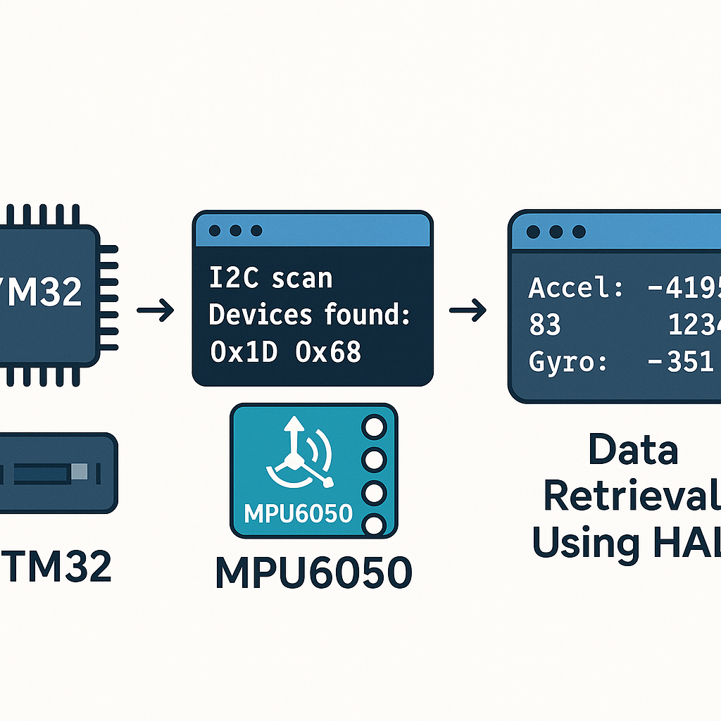
void I2C_Scan(I2C_HandleTypeDef *hi2c) {
    printf("Scanning I2C bus...\r\n");
    uint8_t devices_found = 0;

    for (uint8_t addr = 1; addr < 128; addr++) {
        if (HAL_I2C_IsDeviceReady(hi2c, addr << 1, 2, 10) == HAL_OK) {
            printf("Device found at 0x%02X\r\n", addr);
            devices_found++;
        }
    }

    if (devices_found == 0) {
        printf("No I2C devices found\r\n");
    } else {
        printf("%d device(s) found\r\n", devices_found);
    }
}
The MPU6050 default address is 0x68 (AD0 pin low). If AD0 is pulled high, it shifts to 0x69. When you see 0x68 in your scan output, you know the wiring is good.
Note the
addr << 1in the HAL call. The STM32 HAL expects the 7-bit address left-shifted by one (so 0x68 becomes 0xD0). This is a constant source of confusion—if you pass the raw 7-bit address without shifting,HAL_I2C_IsDeviceReady()will probe the wrong address and find nothing. - In your
- Retrieve data from the MPU6050
- Define the address and key registers:
#define MPU6050_ADDR (0x68 << 1) /* HAL expects left-shifted */ #define WHO_AM_I_REG 0x75 #define PWR_MGMT_1 0x6B #define ACCEL_XOUT_H 0x3B- Wake up the MPU6050 first. It powers on in sleep mode by default—a detail that trips up a lot of people:
void MPU6050_Init(I2C_HandleTypeDef *hi2c) { uint8_t check; HAL_I2C_Mem_Read(hi2c, MPU6050_ADDR, WHO_AM_I_REG, I2C_MEMADD_SIZE_8BIT, &check, 1, 100); if (check == 0x68) { printf("MPU6050 detected\r\n"); /* Wake it up: clear sleep bit in PWR_MGMT_1 */ uint8_t data = 0x00; HAL_I2C_Mem_Write(hi2c, MPU6050_ADDR, PWR_MGMT_1, I2C_MEMADD_SIZE_8BIT, &data, 1, 100); } }- Read the accelerometer data (6 bytes starting at 0x3B):
void MPU6050_Read_Accel(I2C_HandleTypeDef *hi2c,
                        int16_t *ax, int16_t *ay, int16_t *az) {
    uint8_t data[6];
    HAL_I2C_Mem_Read(hi2c, MPU6050_ADDR, ACCEL_XOUT_H,
                     I2C_MEMADD_SIZE_8BIT, data, 6, 100);
    *ax = (int16_t)(data[0] << 8 | data[1]);
    *ay = (int16_t)(data[2] << 8 | data[3]);
    *az = (int16_t)(data[4] << 8 | data[5]);
}
The raw values are 16-bit signed integers. At the default ±2g range, divide by 16384 to get g-force values. If you changed the full-scale range in the ACCEL_CONFIG register (0x1C), the scaling factor changes accordingly.
- Put it all together in main
int main(void) {
    HAL_Init();
    SystemClock_Config();
    MX_GPIO_Init();
    MX_I2C1_Init();
    MX_USART2_UART_Init();  /* for printf output */

    /* Scan the bus first */
    I2C_Scan(&hi2c1);

    /* Initialize MPU6050 */
    MPU6050_Init(&hi2c1);

    int16_t ax, ay, az;
    while (1) {
        MPU6050_Read_Accel(&hi2c1, &ax, &ay, &az);
        printf("X: %d  Y: %d  Z: %d\r\n", ax, ay, az);
        HAL_Delay(100);  /* 10 Hz read rate */
    }
}
With the board sitting flat on a desk, you should see roughly 0 on X and Y, and around +16384 on Z (that's 1g pointing down). If all three axes read zero, the MPU6050 is probably still in sleep mode—go back and verify the
PWR_MGMT_1write.
Troubleshooting
- No devices found during I2C scan:
- Double-check SDA and SCL wiring. Swapped lines are the most common mistake.
- Verify pull-up resistors are present (measure with a multimeter—SDA and SCL should idle high at 3.3V).
- Confirm I2C1 is enabled in CubeMX and the correct pins are assigned.
- Make sure VCC is connected and the MPU6050 power LED (if present) is on.
- Device found but data reads are all zeros:
- You forgot to wake up the MPU6050. Write 0x00 to register 0x6B (PWR_MGMT_1).
- Verify you're reading from the correct register addresses.
- Check that you're using the left-shifted address (0xD0, not 0x68) in HAL calls.
- Data is noisy or erratic:
- Add a small delay after waking the sensor (10-50ms) to let it stabilize.
- Check for loose jumper wire connections causing intermittent contact.
- If running at 400 kHz, try dropping to 100 kHz to rule out signal integrity issues.
Conclusion
You've got a working I2C scanner and MPU6050 accelerometer reader on STM32. The bus scanner is a tool you'll reuse constantly—whenever you wire up a new I2C device, run the scan first to confirm the address before writing any driver code. Next steps from here: read the gyroscope data (registers 0x43-0x48, same pattern), configure the digital low-pass filter, or look into the DMP (Digital Motion Processor) built into the MPU6050 for on-chip sensor fusion.