How to Interface the MPU6050 IMU with STM32 and Arduino
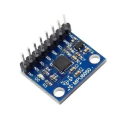
The MPU6050 is a 6-axis IMU (3-axis accelerometer + 3-axis gyroscope) that talks over I2C and costs almost nothing on a GY-521 breakout board. It's been around for years, and while newer sensors exist, the MPU6050 remains one of the best options for learning IMU fundamentals — the register interface is straightforward, libraries are everywhere, and there's a massive community if you get stuck. You can grab a breakout board here: Amazon link.
This guide covers wiring and reading the MPU6050 on both STM32 (using STM32CubeIDE v1.16+ and HAL) and Arduino (using Arduino IDE 2.x). Same sensor, two platforms, so you can pick whichever fits your project.
System Architecture
   +-------------+        +----------------+         +-------------+
   |   MPU6050   | <----> |   MCU (STM32   | <-----> |   PC/Serial |
   | Accel+Gyro  |  I2C   | or Arduino)    |  UART   |  Monitor    |
   +-------------+        +----------------+         +-------------+
- Protocol: I2C (standard mode 100kHz, or fast mode 400kHz)
- Data Flow: MPU6050 → MCU reads registers → prints to serial
- Control Flow: MCU writes config registers on startup, then polls sensor data in a loop
Bill of Materials
- MPU6050 breakout (GY-521 module) — runs on 3.3V or 5V, has onboard regulator and pull-ups
- STM32 board (if going that route) — STM32F103 "Blue Pill" or any Nucleo board works. The code below uses an F103.
- Arduino (if going that route) — Uno, Nano, or any board with I2C pins
- USB-UART adapter (for STM32 serial output) — CP2102 or FT232RL. Not needed for Arduino since it has USB serial built in.
- Jumper wires and optionally a breadboard
Hardware Setup: MPU6050 to STM32F103
MPU6050 Pin    STM32F103 Pin    Notes
-----------    -------------    -----
VCC            3.3V             Blue Pill is 3.3V logic
GND            GND              Common ground
SCL            PB6 (I2C1_SCL)   GY-521 has pull-ups, but add 4.7k external ones for reliability
SDA            PB7 (I2C1_SDA)   Same deal with pull-ups
INT            PA0 (optional)   For motion/data-ready interrupts
AD0            GND              Sets I2C address to 0x68
Tip: the GY-521 breakout board includes 2.2k pull-up resistors already. For short wires on a breadboard, these are usually fine. If you're running longer wires or sharing the I2C bus with other devices, add external 4.7k pull-ups to 3.3V on SDA and SCL.
Hardware Setup: MPU6050 to Arduino Uno
MPU6050 Pin    Arduino Uno Pin    Notes
-----------    ---------------    -----
VCC            5V                 GY-521 has a voltage regulator, 5V input is fine
GND            GND                Common ground
SCL            A5                 Hardware I2C clock
SDA            A4                 Hardware I2C data
INT            D2 (optional)      External interrupt capable pin
AD0            GND                I2C address = 0x68
STM32 Firmware (HAL)
Toolchain: STM32CubeIDE v1.16+. Enable I2C1 and USART1 in the CubeMX configurator, generate the project, then drop this into your main.c:
#include "main.h"
#include <stdio.h>
#include <string.h>

extern I2C_HandleTypeDef hi2c1;
extern UART_HandleTypeDef huart1;

#define MPU6050_ADDR (0x68 << 1)  // HAL expects left-shifted 7-bit address

static uint8_t mpu_buf[14];

void MPU6050_Init(void) {
    uint8_t check, data;

    // Read WHO_AM_I register (0x75) -- should return 0x68
    HAL_I2C_Mem_Read(&hi2c1, MPU6050_ADDR, 0x75, 1, &check, 1, 1000);
    if (check != 0x68) return;  // Wrong device or bad wiring

    // Wake up: clear sleep bit in PWR_MGMT_1
    data = 0x00;
    HAL_I2C_Mem_Write(&hi2c1, MPU6050_ADDR, 0x6B, 1, &data, 1, 1000);

    // Accelerometer config: +/- 8g (0x10)
    data = 0x10;
    HAL_I2C_Mem_Write(&hi2c1, MPU6050_ADDR, 0x1C, 1, &data, 1, 1000);

    // Gyroscope config: +/- 2000 deg/s (0x18)
    data = 0x18;
    HAL_I2C_Mem_Write(&hi2c1, MPU6050_ADDR, 0x1B, 1, &data, 1, 1000);
}

void MPU6050_Read(void) {
    // Burst read 14 bytes starting at ACCEL_XOUT_H (0x3B)
    // Layout: AX_H, AX_L, AY_H, AY_L, AZ_H, AZ_L, TEMP_H, TEMP_L, GX_H, GX_L, GY_H, GY_L, GZ_H, GZ_L
    HAL_I2C_Mem_Read(&hi2c1, MPU6050_ADDR, 0x3B, 1, mpu_buf, 14, 1000);
}

int main(void) {
    HAL_Init();
    SystemClock_Config();
    MX_GPIO_Init();
    MX_I2C1_Init();
    MX_USART1_UART_Init();

    MPU6050_Init();
    char msg[128];

    while (1) {
        MPU6050_Read();

        int16_t ax = (mpu_buf[0] << 8) | mpu_buf[1];
        int16_t ay = (mpu_buf[2] << 8) | mpu_buf[3];
        int16_t az = (mpu_buf[4] << 8) | mpu_buf[5];
        // bytes 6-7 are temperature, skipping
        int16_t gx = (mpu_buf[8] << 8) | mpu_buf[9];
        int16_t gy = (mpu_buf[10] << 8) | mpu_buf[11];
        int16_t gz = (mpu_buf[12] << 8) | mpu_buf[13];

        sprintf(msg, "AX:%d AY:%d AZ:%d GX:%d GY:%d GZ:%d\r\n",
                ax, ay, az, gx, gy, gz);
        HAL_UART_Transmit(&huart1, (uint8_t*)msg, strlen(msg), 1000);
        HAL_Delay(100);
    }
}
The burst read starting at register 0x3B grabs all 14 bytes (accel + temp + gyro) in one I2C transaction. This is faster and more consistent than reading each axis separately, since the MPU6050 can update registers mid-read if you do them one at a time.
Arduino Firmware
Option A: Raw Register Access
This approach talks directly to the MPU6050 registers using the Wire library. No external dependencies, and you learn exactly what's happening on the bus.
#include <Wire.h>
#define MPU6050_ADDR 0x68

void setup() {
    Serial.begin(115200);
    Wire.begin();

    // Wake up the MPU6050 (clear sleep bit)
    Wire.beginTransmission(MPU6050_ADDR);
    Wire.write(0x6B);
    Wire.write(0x00);
    Wire.endTransmission(true);

    // Accel config: +/- 8g
    Wire.beginTransmission(MPU6050_ADDR);
    Wire.write(0x1C);
    Wire.write(0x10);
    Wire.endTransmission(true);

    // Gyro config: +/- 2000 deg/s
    Wire.beginTransmission(MPU6050_ADDR);
    Wire.write(0x1B);
    Wire.write(0x18);
    Wire.endTransmission(true);

    Serial.println("MPU6050 ready");
}

void loop() {
    Wire.beginTransmission(MPU6050_ADDR);
    Wire.write(0x3B);  // Start at ACCEL_XOUT_H
    Wire.endTransmission(false);  // Repeated start, don't release bus
    Wire.requestFrom(MPU6050_ADDR, 14, true);

    int16_t ax = (Wire.read() << 8) | Wire.read();
    int16_t ay = (Wire.read() << 8) | Wire.read();
    int16_t az = (Wire.read() << 8) | Wire.read();
    int16_t temp = (Wire.read() << 8) | Wire.read();  // Temperature, often ignored
    int16_t gx = (Wire.read() << 8) | Wire.read();
    int16_t gy = (Wire.read() << 8) | Wire.read();
    int16_t gz = (Wire.read() << 8) | Wire.read();

    Serial.print("AX: "); Serial.print(ax);
    Serial.print(" AY: "); Serial.print(ay);
    Serial.print(" AZ: "); Serial.print(az);
    Serial.print(" GX: "); Serial.print(gx);
    Serial.print(" GY: "); Serial.print(gy);
    Serial.print(" GZ: "); Serial.println(gz);

    delay(200);
}
Option B: Using the MPU6050 Library
If you just want data fast, install the "MPU6050" library by Electronic Cats via the Arduino IDE 2.x Library Manager. It wraps all the register access for you:
#include <Wire.h>
#include <MPU6050.h>

MPU6050 mpu;

void setup() {
    Serial.begin(115200);
    Wire.begin();
    mpu.initialize();

    if (mpu.testConnection())
        Serial.println("MPU6050 connected");
    else
        Serial.println("MPU6050 connection failed");
}

void loop() {
    int16_t ax, ay, az, gx, gy, gz;
    mpu.getMotion6(&ax, &ay, &az, &gx, &gy, &gz);

    Serial.print("AX="); Serial.print(ax);
    Serial.print(" AY="); Serial.print(ay);
    Serial.print(" AZ="); Serial.print(az);
    Serial.print(" GX="); Serial.print(gx);
    Serial.print(" GY="); Serial.print(gy);
    Serial.print(" GZ="); Serial.println(gz);

    delay(200);
}
Testing Your Setup
Upload the code and open your serial terminal at 115200 baud. Place the board flat on a table. You should see the Z-axis accelerometer reading near +1g (roughly 4096 at +/-8g sensitivity, or 16384 at +/-2g). The X and Y accel values should be close to zero, and all gyro values should be near zero when the board is stationary.
Pick up the board and tilt it around. The accelerometer values should shift as gravity's vector changes relative to the sensor axes. Rotate the board quickly and you'll see the gyro readings spike. If everything responds to motion, your wiring and configuration are good.
Troubleshooting
- No I2C ACK (HAL returns HAL_ERROR, or Wire gets no response): Check your wiring first. Then confirm the I2C address — it's 0x68 with AD0 tied to GND, or 0x69 with AD0 tied to VCC. Run an I2C scanner sketch to verify the device is visible on the bus.
- Data looks like random noise: Make sure you're combining the high and low bytes in the right order (big-endian — high byte first). Also verify your power supply is stable and decoupled. A 100nF cap close to the MPU6050's VCC pin helps.
- Gyro readings drift over time: This is normal for MEMS gyroscopes. Read ~1000 samples at startup while the board is stationary, average them, and subtract that bias from all future readings. This simple calibration makes a big difference.
- STM32 I2C bus locks up: The STM32F103's I2C peripheral is notorious for this. If the bus hangs, toggle the SCL line manually a few times via GPIO to unstick it, then reinitialize I2C. Some developers add a bus-recovery routine that runs on timeout.
Converting Raw Values to Real Units
The raw values from the MPU6050 are just ADC counts. To get meaningful numbers, divide by the sensitivity scale factor from the datasheet:
- Accelerometer at +/-8g: divide raw value by 4096 to get g's
- Gyroscope at +/-2000 deg/s: divide raw value by 16.4 to get degrees per second
If you changed the range settings, the scale factors change too. Check Table 1 and Table 2 in the MPU6050 register map document for all the options.
Next Steps
- Sensor fusion: Raw accel and gyro data alone are noisy and drift-prone. Use a Madgwick or Mahony filter to fuse them into stable roll/pitch/yaw angles. There are Arduino libraries for both.
- Wireless motion tracking: Pair the MPU6050 with an ESP32 (which has built-in WiFi and BLE) to stream orientation data wirelessly. The ESP32 Arduino core v3.x supports the Wire library just like a regular Arduino.
- 3D visualization: Send the orientation data to a Processing sketch or a Python script using matplotlib or vpython to see the sensor orientation in real time.
- Upgrade to ICM-42688-P or BMI270: If you need better accuracy, lower noise, or a built-in sensor fusion engine, these newer IMUs are worth a look. The MPU6050 is great for learning, but it's been EOL'd by InvenSense — the ICM series is the successor.