How to Implement STM32 I2C Interface for VL53L0X Distance Sensing at 50Hz
Why the VL53L0X at 50Hz?
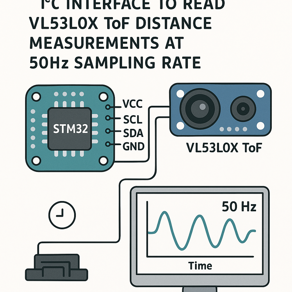
The VL53L0X is a Time-of-Flight laser ranging sensor that gives you millimeter-accurate distance measurements from 30mm out to about 2 meters. ST makes both the sensor and the STM32, so the I2C integration is well-supported. At 50Hz (one reading every 20ms), you get smooth enough data for gesture detection, obstacle avoidance, or liquid level monitoring.
The trick is getting consistent 50Hz sampling without blocking your main loop. We'll use an STM32 hardware timer to trigger readings at a fixed interval, keeping everything deterministic.
Prerequisites
- STM32CubeIDE v1.16+ installed and working
- Familiarity with C and basic STM32 peripheral configuration
- An STM32 dev board (Nucleo-F401RE, Nucleo-F446RE, or similar F4/G4 boards work well)
- Understanding of I2C basics (clock, data, addressing)
Parts/Tools
- STM32 Nucleo or Discovery board
- VL53L0X breakout board (Pololu, Adafruit, or generic—they all use the same ST chip)
- Jumper wires
- USB cable for programming and serial debug
- Logic analyzer (optional but very handy for I2C debugging)
Steps
- Wire the VL53L0X to the STM32
Four wires total. The VL53L0X breakout boards include pull-up resistors and a voltage regulator, so you can connect directly:
- VCC on VL53L0X to 3.3V on STM32
- GND on VL53L0X to GND on STM32
- SDA on VL53L0X to PB7 (I2C1_SDA on most F4 boards)
- SCL on VL53L0X to PB6 (I2C1_SCL on most F4 boards)
Watch out: if you're using a bare VL53L0X module without a breakout board, you'll need external 4.7k pull-ups on SDA and SCL. The breakout boards from Pololu and Adafruit already have these.
- Configure the STM32 project in CubeIDE
Create a new STM32 project targeting your specific board. In the .ioc pinout configurator:
- Enable I2C1 in standard mode (100kHz is fine for the VL53L0X; fast mode 400kHz works too if you need the headroom)
- Enable TIM2 (or another general-purpose timer) with a period that gives you a 50Hz interrupt—set the prescaler and ARR so the timer overflows every 20ms
- Enable USART2 for serial debug output (Nucleo boards route this through the ST-Link USB)
- Enable the TIM2 global interrupt in NVIC settings
Generate the code. CubeIDE will scaffold all the HAL initialization for you.
- Add the VL53L0X driver
ST provides an official API for the VL53L0X (search for "STSW-IMG005" on st.com, or grab it from the ST GitHub repo). Copy the
coreandplatformfolders into your project'sDriversdirectory.You'll need to implement the platform abstraction layer—basically a handful of functions that map ST's API to HAL I2C calls. The key ones are
VL53L0X_WriteMulti,VL53L0X_ReadMulti, andVL53L0X_WaitMs. Here's the I2C read/write pattern:VL53L0X_Error VL53L0X_WriteMulti(VL53L0X_DEV Dev, uint8_t index, uint8_t *pdata, uint32_t count) { return HAL_I2C_Mem_Write(&hi2c1, Dev->I2cDevAddr, index, I2C_MEMADD_SIZE_8BIT, pdata, count, 100) == HAL_OK ? VL53L0X_ERROR_NONE : VL53L0X_ERROR_CONTROL_INTERFACE; } VL53L0X_Error VL53L0X_ReadMulti(VL53L0X_DEV Dev, uint8_t index, uint8_t *pdata, uint32_t count) { return HAL_I2C_Mem_Read(&hi2c1, Dev->I2cDevAddr, index, I2C_MEMADD_SIZE_8BIT, pdata, count, 100) == HAL_OK ? VL53L0X_ERROR_NONE : VL53L0X_ERROR_CONTROL_INTERFACE; } - Initialize the sensor
In your
main(), after the HAL and peripheral init, add the VL53L0X initialization sequence. The API requires a specific startup sequence—data init, static init, reference calibration:VL53L0X_Dev_t vl53l0x_dev; VL53L0X_DEV Dev = &vl53l0x_dev; Dev->I2cDevAddr = 0x52; // 0x29 shifted left by 1 for HAL Dev->comms_type = 1; // I2C VL53L0X_DataInit(Dev); VL53L0X_StaticInit(Dev); uint32_t refSpadCount; uint8_t isApertureSpads; VL53L0X_PerformRefSpadManagement(Dev, &refSpadCount, &isApertureSpads); uint8_t VhvSettings, PhaseCal; VL53L0X_PerformRefCalibration(Dev, &VhvSettings, &PhaseCal); VL53L0X_SetDeviceMode(Dev, VL53L0X_DEVICEMODE_CONTINUOUS_RANGING); VL53L0X_StartMeasurement(Dev);Note the I2C address: the VL53L0X's 7-bit address is 0x29, but the STM32 HAL expects the 8-bit (left-shifted) address, which is 0x52. This trips people up constantly.
- Set up the 50Hz timer callback
Start TIM2 in interrupt mode in
main():HAL_TIM_Base_Start_IT(&htim2);Then implement the timer callback to read measurements:
volatile uint16_t g_distance_mm = 0;
volatile uint8_t g_new_data = 0;

void HAL_TIM_PeriodElapsedCallback(TIM_HandleTypeDef *htim) {
    if (htim->Instance == TIM2) {
        VL53L0X_RangingMeasurementData_t measurement;
        VL53L0X_GetRangingMeasurementData(Dev, &measurement);

        if (measurement.RangeStatus != 4) { // 4 = out of range
            g_distance_mm = measurement.RangeMilliMeter;
            g_new_data = 1;
        }
    }
}
A practical tip: I'm using continuous ranging mode here because it lets the sensor free-run and you just grab the latest result when the timer fires. This is simpler than single-shot mode and ensures the sensor is always ready with fresh data. The tradeoff is slightly higher power consumption, which usually doesn't matter for a wired dev board setup.
- Process and output the data
In your main loop, check the flag and print the distance:
while (1) { if (g_new_data) { g_new_data = 0; char buf[32]; sprintf(buf, "Distance: %u mm\r\n", g_distance_mm); HAL_UART_Transmit(&huart2, (uint8_t*)buf, strlen(buf), 100); } } - Build and flash
Build the project in STM32CubeIDE (Ctrl+B) and flash it via the ST-Link debugger (F11 to debug, or Ctrl+F11 to just run). Open a serial terminal at the baud rate you configured for USART2 (115200 is the standard choice).
Move your hand in front of the sensor—you should see distance values updating at a steady 50Hz clip.
Troubleshooting
- No I2C response at all: First, scan the bus. Write a quick loop that tries
HAL_I2C_IsDeviceReady()for addresses 0x00 through 0xFE. If the VL53L0X doesn't show up, your wiring is wrong or the sensor isn't getting power. Check with a multimeter that 3.3V is actually reaching the module. - Getting readings of 0 or 8190: A reading of 8190 usually means the sensor is out of range or seeing nothing reflective enough. A reading of 0 often means the initialization sequence wasn't run completely. Make sure you're doing the full data init, static init, SPAD management, and ref calibration in order.
- Inconsistent timing: If your 50Hz isn't accurate, double-check your timer prescaler and ARR values. For a 84MHz APB1 clock (typical for STM32F4), a prescaler of 8399 and ARR of 199 gives you exactly 50Hz: 84,000,000 / (8400 * 200) = 50.
- I2C bus hangs: The VL53L0X can occasionally hold SDA low and lock up the bus. A workaround is to toggle SCL manually a few times at startup to clear the condition. Some people add a GPIO-controlled reset to the sensor's XSHUT pin for a hard reset option.
- Noisy readings: The VL53L0X raw output can jump around by 10-20mm. If you need smoother data, apply a simple moving average or exponential filter on the readings. Five to ten samples is usually enough to settle things down.
Where to Go From Here
You've got reliable 50Hz distance sensing working over I2C. Some natural extensions: use the XSHUT pin to put multiple VL53L0X sensors on the same I2C bus (each gets a unique address at startup), add DMA-based I2C transfers to free up the CPU, or integrate the readings into a FreeRTOS task if you're building a larger application. The VL53L1X is the newer sensor in this family and extends the range to about 4 meters if you need more distance.