How to Implement PWM Current Limiting for DC Motors with STM32F4 H-Bridge
Why PWM Current Limiting Matters
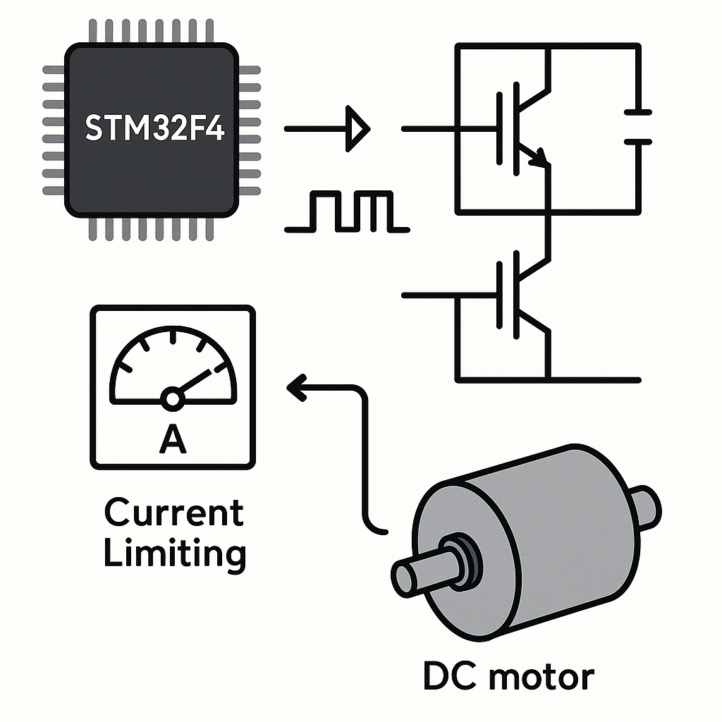
DC motors draw whatever current they need to maintain speed under load. If you don't limit that current, a stalled motor can pull enough amps to fry your H-bridge, overheat windings, or pop a fuse. PWM-based current limiting gives you a feedback loop: measure the actual motor current, compare it to your limit, and back off the duty cycle when things get too hot.
This tutorial covers how to set up an STM32F4 with an H-bridge driver, a shunt resistor for current sensing, and a control loop that throttles PWM duty cycle to keep current within safe bounds.
Prerequisites
- Comfortable with C and basic STM32 HAL programming
- Understanding of PWM and duty cycle concepts
- Familiarity with H-bridge operation (how IN1/IN2/ENA pins control direction and speed)
- STM32CubeIDE v1.16+ installed
Parts and Tools
- STM32F4 development board (Nucleo-F446RE, Discovery, etc.)
- H-bridge module — L298N is fine for prototyping, but for anything serious consider a DRV8871 or BTS7960 which have built-in current sensing
- DC motor with known current rating
- Low-value shunt resistor (0.1Ω to 0.5Ω, rated for your motor's current)
- Power supply matched to your motor's voltage and current specs
- Breadboard, jumper wires, multimeter
Steps
- Wire the Hardware
Connect the H-bridge to your STM32F4 like this:
STM32F4 Pin     H-Bridge Pin
-----------     ------------
TIM PWM Out     ENA (Enable A)
GPIO Pin A      IN1
GPIO Pin B      IN2
Connect the DC motor to the H-bridge output terminals. Place a low-value shunt resistor (say 0.1Ω) in series between the motor's ground return and the actual ground rail. The voltage across this resistor is proportional to the motor current (V = I × R).
Connect the high side of the shunt resistor to an STM32F4 ADC input pin. If the expected voltage is tiny (e.g., 0.1Ω × 1A = 100mV), you may want an op-amp gain stage. For prototyping with low-current motors, you can often read it directly.
Watch out: the L298N has a significant voltage drop (~2V per transistor). Factor that into your power budget. For motors above 2A, the L298N gets hot fast — consider a MOSFET-based driver instead.
- Configure the STM32F4 in CubeIDE
- Create a new project in STM32CubeIDE for your board.
- In CubeMX, configure a timer channel (e.g., TIM1 CH1) in PWM Generation mode.
- Set the timer prescaler and auto-reload to get your desired PWM frequency. For DC motors, 20kHz is a solid starting point — it's above the audible range so the motor won't whine.
- Configure an ADC channel (e.g., ADC1 IN0) for the shunt resistor voltage input.
- Set the ADC to 12-bit resolution. If you want continuous sampling, set up DMA for the ADC.
- Generate the code.
- Implement Current Sensing
Read the shunt voltage via ADC and convert it to current. Here's a straightforward approach:
#define V_REF         3.3f
#define ADC_MAX       4095.0f
#define SHUNT_RESISTOR 0.1f  // ohms

float readMotorCurrent(void)
{
    HAL_ADC_Start(&hadc1);
    HAL_ADC_PollForConversion(&hadc1, 10);
    uint32_t adcRaw = HAL_ADC_GetValue(&hadc1);
    float voltage = (adcRaw * V_REF) / ADC_MAX;
    return voltage / SHUNT_RESISTOR;
}
Tip:
HAL_ADC_PollForConversionis blocking. For a real motor control loop, set up the ADC with DMA or use interrupt-driven conversion so you're not stalling your main loop. If you're running FreeRTOS (v11.x), do the ADC read in a dedicated task. - Implement the Current Limiting Loop
Define your max current threshold and write a control loop that reduces the duty cycle when current exceeds the limit:
#define MAX_CURRENT   1.0f   // amps
#define PWM_MAX       999    // auto-reload value (match your timer config)

void setDutyCycle(uint32_t duty)
{
    if (duty > PWM_MAX) duty = PWM_MAX;
    __HAL_TIM_SET_COMPARE(&htim1, TIM_CHANNEL_1, duty);
}

uint32_t targetDuty = 500;  // desired speed

// In your main loop or a periodic timer callback:
void currentLimitLoop(void)
{
    float current = readMotorCurrent();
    if (current > MAX_CURRENT)
    {
        // Back off proportionally
        uint32_t reducedDuty = (uint32_t)(targetDuty * (MAX_CURRENT / current));
        setDutyCycle(reducedDuty);
    }
    else
    {
        setDutyCycle(targetDuty);
    }
}
This is a simple proportional limiter. For smoother control, implement a proper PI loop where you integrate the error over time. The proportional-only approach can oscillate around the limit — adding an integral term smooths that out.
Also make sure you start the timer and PWM output before entering the loop:
HAL_TIM_PWM_Start(&htim1, TIM_CHANNEL_1);
Troubleshooting
- Motor doesn't spin: Verify IN1 and IN2 are set correctly for your desired direction (one HIGH, one LOW). Check that ENA is actually receiving the PWM signal with an oscilloscope or logic analyzer.
- ADC reads zero or garbage: Confirm the ADC pin is wired to the correct side of the shunt resistor. Make sure the ADC clock is enabled and the channel is properly configured in CubeMX.
- Current readings are way off: Double-check your shunt resistor value. Verify V_REF matches your board's actual reference voltage (measure it — it's not always exactly 3.3V). If the shunt voltage is very small, ADC noise will dominate — add averaging or a hardware amplifier.
- Motor stalls under load: Your current limit might be set too low for the motor's operating range. Check the motor's stall current spec and set MAX_CURRENT below that but above the running current.
- Audible whine from the motor: Your PWM frequency is in the audible range. Bump it to 20kHz or higher.
Wrapping Up
PWM current limiting is a fundamental technique for any motor control project. The basic version here — shunt resistor, ADC read, proportional limit — will get you running safely. For production systems, you'd want hardware overcurrent protection (a comparator that kills the PWM output instantly), proper PCB layout for the shunt resistor, and a more sophisticated control loop. But as a starting point for prototyping and learning, this gets the job done.