How to Implement PWM Control for DC Fans and RGB LEDs with STM32 TIM2
Why PWM for Fans and LEDs
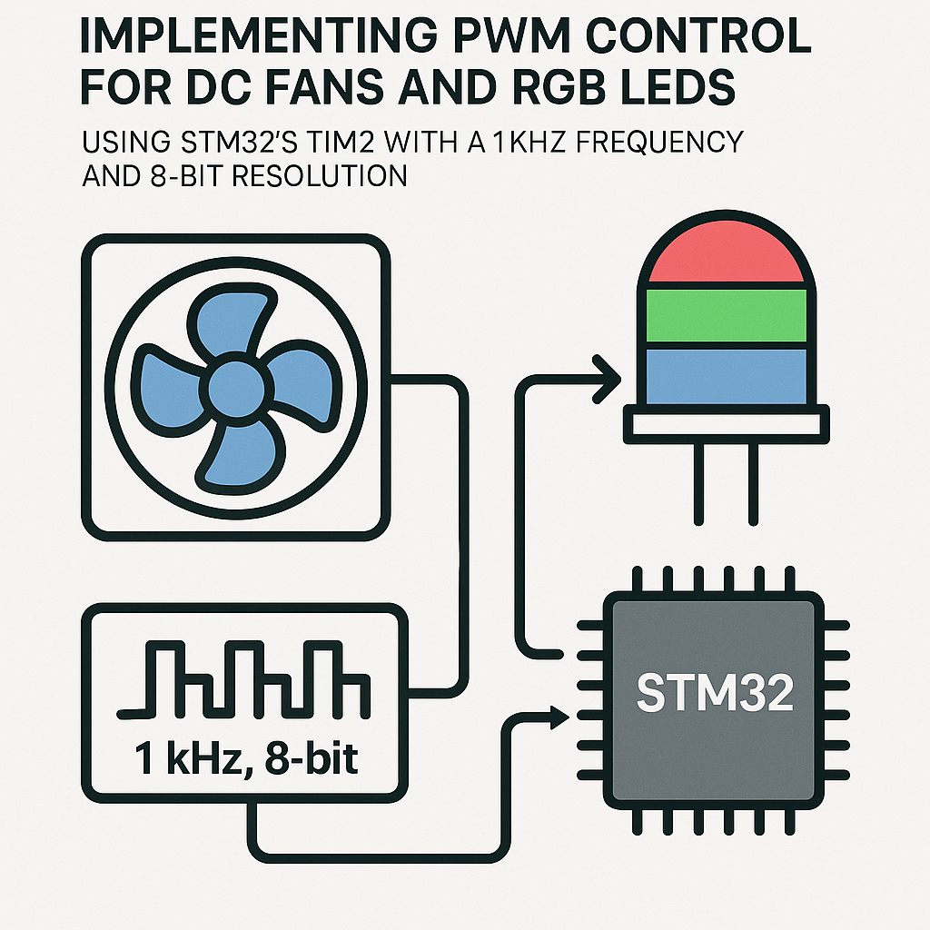
PWM (Pulse Width Modulation) is how you get analog-like control out of a digital pin. Instead of the pin being fully on or fully off, you rapidly toggle it and vary the ratio of on-time to off-time. Your DC fan sees an average voltage and spins slower or faster. Your RGB LED sees an average current and dims or brightens. The human eye and a motor's inertia do the smoothing for you.
The STM32's hardware timers make this dead simple. TIM2 has four output channels, which is perfect: one for your fan and three for an RGB LED. We'll configure it for 1 kHz at 8-bit resolution (0-255 duty cycle values), which is a solid baseline for both fan and LED control.
Prerequisites
- Basic C programming and familiarity with STM32 development
- An STM32 development board (STM32F4, STM32F1, STM32G4, etc. -- any chip with TIM2)
- STM32CubeIDE (v1.16+) installed
- A DC fan and an RGB LED (common cathode)
Parts/Tools
- STM32 Development Board
- Small DC fan (5V or 12V, depending on your power supply)
- Common cathode RGB LED
- 3x 220-ohm resistors (for the LED)
- N-channel MOSFET or transistor (to drive the fan from a PWM pin)
- Jumper wires and a breadboard
Steps
- Create a New Project in STM32CubeIDE
Open STM32CubeIDE and start a new STM32 project. Select your specific microcontroller from the chip selector. The integrated CubeMX configurator will open automatically.
- Configure TIM2 for PWM Output
In the Pinout & Configuration view, find TIM2 under Timers and enable it. Set each channel you need:
- Channel 1: PWM Generation (for the DC fan)
- Channels 2, 3, 4: PWM Generation (for Red, Green, Blue)
Now set the timer parameters. For 1 kHz PWM with 8-bit resolution, you need the prescaler and auto-reload values to work together with your clock speed.
Assuming an 84 MHz APB1 timer clock (common on STM32F4):
- Prescaler: 328 (so the timer ticks at 84 MHz / (328+1) = ~255.3 kHz)
- Counter Period (ARR): 255 (giving 255.3 kHz / 256 = ~1 kHz)
Gotcha: The prescaler and ARR registers are zero-indexed, so a value of 255 means the counter counts from 0 to 255 (256 steps). Double check your chip's actual APB1 timer clock -- it depends on your clock tree configuration. Open the Clock Configuration tab in CubeMX to verify.
- Generate Code and Start PWM
Click "Generate Code" to create your project files. In
main.c, after the auto-generated initialization calls, start the PWM channels:/* Start PWM on all four channels */ HAL_TIM_PWM_Start(&htim2, TIM_CHANNEL_1); // DC fan HAL_TIM_PWM_Start(&htim2, TIM_CHANNEL_2); // Red HAL_TIM_PWM_Start(&htim2, TIM_CHANNEL_3); // Green HAL_TIM_PWM_Start(&htim2, TIM_CHANNEL_4); // BluePlace this code in the
/* USER CODE BEGIN 2 */section so it doesn't get overwritten if you regenerate from CubeMX. - Set the Duty Cycle
To control the outputs, write a compare value between 0 and 255 for each channel:
/* Fan at 50% speed */
__HAL_TIM_SET_COMPARE(&htim2, TIM_CHANNEL_1, 128);

/* RGB LED: purple (red + blue, no green) */
__HAL_TIM_SET_COMPARE(&htim2, TIM_CHANNEL_2, 200); // Red
__HAL_TIM_SET_COMPARE(&htim2, TIM_CHANNEL_3, 0);   // Green off
__HAL_TIM_SET_COMPARE(&htim2, TIM_CHANNEL_4, 180); // Blue
You can call
__HAL_TIM_SET_COMPARE()at any time to change the duty cycle on the fly -- in your main loop, from a button callback, from a UART command handler, wherever. - Wire Up the Hardware
Check your datasheet or CubeMX's pin view to find which GPIO pins TIM2's channels map to. On many STM32F4 boards:
- TIM2_CH1 = PA0
- TIM2_CH2 = PA1
- TIM2_CH3 = PA2 (or PB10, depending on alternate function mapping)
- TIM2_CH4 = PA3
For the RGB LED, connect each channel pin through a 220-ohm resistor to the corresponding LED anode. Connect the common cathode to GND.
Watch out: STM32 GPIO pins can only source about 20-25 mA. That's fine for LEDs, but absolutely not enough to drive a DC fan directly. Use an N-channel MOSFET (like an IRLZ44N or 2N7000 for smaller fans) between the PWM pin and the fan. The PWM signal drives the gate, and the MOSFET switches the fan's power supply.
- Build, Flash, and Test
Compile with Ctrl+B and flash to your board. You should see the fan spinning at half speed and the LED glowing purple. Try sweeping the duty cycle in a loop to see smooth fading:
for (uint8_t i = 0; i < 255; i++) {
    __HAL_TIM_SET_COMPARE(&htim2, TIM_CHANNEL_2, i);
    HAL_Delay(10);
}
Troubleshooting
- Fan Not Spinning:
- Make sure you're driving the fan through a MOSFET, not directly from the GPIO pin.
- Verify the PWM channel is actually started with
HAL_TIM_PWM_Start(). - Check if the fan needs a minimum duty cycle to overcome static friction and start spinning (often around 20-30%).
- LEDs Not Lighting Up:
- Confirm the GPIO alternate function mapping. CubeMX should handle this, but double check the pin assignment.
- Make sure your resistors aren't too high. 220 ohm is typical for 3.3V logic driving standard LEDs.
- Test with a fixed duty cycle of 255 (full on) to rule out duty cycle issues.
- Flickering or Wrong Brightness:
- Check your prescaler and ARR math. An incorrect clock assumption gives you the wrong PWM frequency.
- Make sure duty cycle values don't exceed your ARR value (255 in our case).
- Verify the clock tree in CubeMX -- the APB1 timer clock might not be what you expect if you've changed the PLL settings.
Going Further
With this basic PWM setup working, you've got a foundation for a lot of projects. Add an ADC reading from a potentiometer to make a manual fan speed controller. Implement HSV-to-RGB conversion for smoother color cycling on the LED. Or hook up a temperature sensor and build a closed-loop fan controller that adjusts speed based on heat. The hardware timer handles all the PWM timing in the background, so your CPU is free to do the interesting stuff.