How to Implement Kalman Filter for MPU6050 Sensor Fusion on STM32
Why Kalman Filtering Makes Your MPU6050 Data Actually Usable
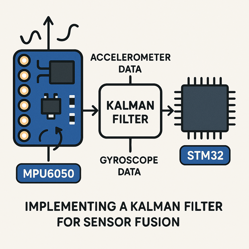
Raw accelerometer data is noisy. Raw gyroscope data drifts. Use either one alone and your orientation estimates will be garbage within seconds. The Kalman filter fixes this by mathematically fusing both sensors together, playing their strengths against each other's weaknesses. The accelerometer gives you a noisy but drift-free gravity reference, while the gyro gives you clean short-term rotation data that slowly wanders off. Combine them with a Kalman filter, and you get stable, accurate angle estimates.
Here's how to implement one on an STM32 using the MPU6050 over I2C.
Prerequisites
- Working knowledge of C programming
- Familiarity with STM32 HAL and STM32CubeIDE (v1.16+)
- MPU6050 sensor module
- Basic understanding of I2C communication
Parts/Tools
- STM32 microcontroller (STM32F4 or STM32F1 series work well)
- MPU6050 breakout board
- Jumper wires
- STM32CubeIDE (v1.16+) installed on your computer
- USB cable or power supply
Steps
- Wire up the hardware
Connect the MPU6050 to your STM32's I2C pins. Most breakout boards already have pull-up resistors on SDA and SCL, but double-check yours. If your board doesn't have them, add 4.7k pull-ups to 3.3V on both lines.
SDA (MPU6050) → SDA (STM32)
SCL (MPU6050) → SCL (STM32)
VCC (MPU6050) → 3.3V (STM32)
GND (MPU6050) → GND (STM32)
Watch out: the MPU6050 runs at 3.3V. Some cheap breakout boards have a voltage regulator and can take 5V on VCC, but the I2C lines are still 3.3V logic. Don't feed 5V I2C signals into a 3.3V STM32 GPIO without level shifting.
- Create and configure the STM32CubeIDE project
Fire up STM32CubeIDE and create a new STM32 project for your target MCU. In the .ioc configuration file, enable one of the I2C peripherals (I2C1 is typical). Set the speed to 400kHz (Fast Mode) — the MPU6050 supports it and you'll get snappier reads. Generate the project code.
- Implement MPU6050 I2C read functions
You need to pull raw 16-bit values for all three accelerometer axes and all three gyro axes. Each axis is stored as two bytes (high byte first) in consecutive registers. Here's a straightforward approach:
#define MPU6050_ADDR 0x68
#define ACCEL_XOUT_H 0x3B
#define GYRO_XOUT_H  0x43

static uint8_t readByte(I2C_HandleTypeDef *hi2c, uint8_t reg) {
    uint8_t data;
    HAL_I2C_Mem_Read(hi2c, MPU6050_ADDR << 1, reg, 1, &data, 1, HAL_MAX_DELAY);
    return data;
}

void MPU6050_ReadAll(I2C_HandleTypeDef *hi2c,
                     int16_t *ax, int16_t *ay, int16_t *az,
                     int16_t *gx, int16_t *gy, int16_t *gz) {
    uint8_t buf[14];
    HAL_I2C_Mem_Read(hi2c, MPU6050_ADDR << 1,
                     ACCEL_XOUT_H, 1, buf, 14, HAL_MAX_DELAY);
    *ax = (int16_t)(buf[0]  << 8 | buf[1]);
    *ay = (int16_t)(buf[2]  << 8 | buf[3]);
    *az = (int16_t)(buf[4]  << 8 | buf[5]);
    // buf[6..7] is temperature, skip it
    *gx = (int16_t)(buf[8]  << 8 | buf[9]);
    *gy = (int16_t)(buf[10] << 8 | buf[11]);
    *gz = (int16_t)(buf[12] << 8 | buf[13]);
}
Pro tip: read all 14 bytes in one burst transaction instead of calling readByte 12 times. Burst reads are faster and keep the data temporally consistent (all samples from the same measurement cycle). The registers from 0x3B to 0x48 are contiguous — accel, temp, then gyro.
- Implement the Kalman filter
This is a simplified 1D Kalman filter. It works per-axis. The two tuning knobs are
q(process noise — how much you expect the true value to change between samples) andr(measurement noise — how noisy your sensor readings are). Smallerrrelative toqmeans you trust the sensor more; largerrmeans you smooth more aggressively.typedef struct { float q; // Process noise covariance float r; // Measurement noise covariance float x; // Estimated value float p; // Estimation error covariance float k; // Kalman gain } KalmanFilter; void Kalman_Init(KalmanFilter *kf, float q, float r) { kf->q = q; kf->r = r; kf->x = 0.0f; kf->p = 1.0f; } float Kalman_Update(KalmanFilter *kf, float measurement) { // Prediction step kf->p += kf->q; // Update step kf->k = kf->p / (kf->p + kf->r); kf->x += kf->k * (measurement - kf->x); kf->p *= (1.0f - kf->k); return kf->x; }The math here is textbook Kalman for a scalar state with no control input. If you want a proper 2-state filter that fuses angle from the accelerometer with angular rate from the gyro (which is the real win for orientation estimation), you'd extend the state to include bias. But this 1D version is a solid starting point and surprisingly effective for many projects.
- Fuse the sensor data in your main loop
Create separate filter instances for each axis (or each angle) you care about. The example below filters raw accel and gyro readings independently, but in a real orientation system you'd typically compute an angle from the accelerometer (using
atan2) and fuse that with the integrated gyro rate.KalmanFilter kf_pitch, kf_roll; Kalman_Init(&kf_pitch, 0.001f, 0.03f); Kalman_Init(&kf_roll, 0.001f, 0.03f); int16_t ax, ay, az, gx, gy, gz; uint32_t last_tick = HAL_GetTick(); while (1) { MPU6050_ReadAll(&hi2c1, &ax, &ay, &az, &gx, &gy, &gz); // Compute pitch/roll from accelerometer (in degrees) float accel_pitch = atan2f((float)ay, sqrtf((float)ax*ax + (float)az*az)) * 57.2958f; float accel_roll = atan2f((float)ax, sqrtf((float)ay*ay + (float)az*az)) * 57.2958f; float pitch = Kalman_Update(&kf_pitch, accel_pitch); float roll = Kalman_Update(&kf_roll, accel_roll); // Use pitch and roll for your application HAL_Delay(10); // ~100 Hz sample rate }Start with
q = 0.001andr = 0.03and adjust from there. If the output is too sluggish, increaseqor decreaser. If it's too jittery, do the opposite. There's no single "right" value — it depends on your sensor mounting, vibration environment, and how fast your system actually moves.
Troubleshooting
- Sensor not responding on I2C: Verify your wiring. Run an I2C scanner to confirm the MPU6050 shows up at address 0x68 (or 0x69 if the AD0 pin is pulled high). Also make sure you're writing to the power management register (0x6B) to wake the sensor out of sleep mode on startup — it boots in sleep by default.
- Filtered output is laggy or still noisy: Tune
qandr. These values are application-specific. Logging raw vs. filtered data to a serial plotter (the one built into STM32CubeIDE or Arduino's Serial Plotter) helps you visualize what the filter is doing. - Build errors about HAL functions: Make sure your .ioc file has I2C enabled and that you've regenerated code after changes. Check that
stm32f4xx_hal_i2c.h(or the equivalent for your MCU family) is included.
Where to Go from Here
This 1D filter gets you started, but for a real IMU project — a drone flight controller, a balancing robot, motion tracking — look into the full 2-state Kalman filter or a complementary filter. The complementary filter is simpler, performs nearly as well for pitch/roll, and uses way less math. For yaw estimation (heading), you'll eventually want a magnetometer and a full attitude estimation algorithm like a Madgwick or Mahony filter. But understanding the basic Kalman mechanics here gives you the foundation for all of that.