How to Implement ESP32 Deep Sleep Mode for Battery-Efficient IoT Monitoring
ESP32 Deep Sleep with GPIO Wakeup for Battery-Powered IoT Monitoring
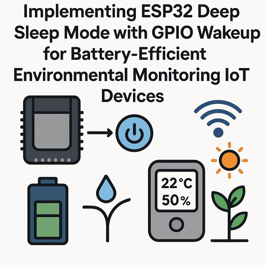
Battery-powered IoT sensors spend most of their life doing absolutely nothing. A temperature reading every 30 seconds doesn't need the full ESP32 burning 150-240 mA continuously. Deep sleep drops that to around 10 microamps. That's the difference between your sensor lasting a week on a battery versus lasting over a year.
This guide covers setting up ESP32 deep sleep with both timer-based and GPIO-based wakeup for an environmental monitoring sensor. You'll get real sensor readings, ship them wherever they need to go, and immediately go back to sleep.
Prerequisites
- Arduino IDE 2.x installed, or PlatformIO v6.x (either works)
- ESP32 development board (any variant - ESP32, ESP32-S3, ESP32-C3)
- A sensor for environmental monitoring (DHT22 or BME280 recommended over the DHT11 for better accuracy)
- USB cable for programming
- Jumper wires and breadboard
Parts/Tools
- ESP32 development board
- DHT22 (or BME280 via I2C if you want pressure data too)
- Arduino IDE 2.x with ESP32 board support, or PlatformIO
- 10K pull-up resistor for the DHT22 data line (some breakout boards include this)
Steps
- Set Up Your Development Environment
- If using Arduino IDE 2.x, add the ESP32 board package. Go to File > Preferences and add the board manager URL:
Note: the oldhttps://espressif.github.io/arduino-esp32/package_esp32_index.jsondl.espressif.comURL still works but redirects to this one. Use the new URL for the Arduino ESP32 core v3.x releases. - Open Tools > Board > Boards Manager, search for "esp32", and install the latest ESP32 Arduino core (v3.x as of early 2026).
- Select your specific board under Tools > Board > esp32.
- If you prefer PlatformIO v6.x, create a new project with the
espressif32platform and your board. PlatformIO handles dependencies much more cleanly for larger projects.
- If using Arduino IDE 2.x, add the ESP32 board package. Go to File > Preferences and add the board manager URL:
- Wire Up the Sensor
- Connect the DHT22 to the ESP32:
- VCC to 3.3V
- GND to GND
- Data to GPIO 4 (with a 10K pull-up resistor to 3.3V)
- Watch out: don't use GPIO 12 for your sensor on the original ESP32. It's a strapping pin that affects flash voltage on boot. GPIOs 4, 13, 14, 15, 25, 26, 27 are safe choices for deep sleep wakeup on the base ESP32. On the ESP32-S3 and C3, the safe pins differ - check the datasheet for your specific variant.
- Connect the DHT22 to the ESP32:
- Install Necessary Libraries
- In Arduino IDE: Sketch > Include Library > Manage Libraries
- Install "DHT sensor library" by Adafruit
- Install "Adafruit Unified Sensor" (it's a dependency)
- If you went with a BME280 instead, install "Adafruit BME280 Library" and the unified sensor library.
- Write the Code
- Here's a proper deep sleep implementation. A few things to understand first: in deep sleep, the ESP32 loses all RAM contents except for RTC memory. When it wakes up, it runs through
setup()again from scratch. So structure your code with that in mind -loop()will never actually execute.#include <DHT.h> #define DHTPIN 4 #define DHTTYPE DHT22 #define SLEEP_DURATION_US 30 * 1000000ULL // 30 seconds in microseconds #define WAKEUP_GPIO GPIO_NUM_33 // External interrupt pin // Store data in RTC memory so it survives deep sleep RTC_DATA_ATTR int bootCount = 0; DHT dht(DHTPIN, DHTTYPE); void setup() { Serial.begin(115200); delay(100); // Give serial a moment bootCount++; Serial.printf("Boot #%d\n", bootCount); // Print wakeup reason esp_sleep_wakeup_cause_t wakeupReason = esp_sleep_get_wakeup_cause(); switch (wakeupReason) { case ESP_SLEEP_WAKEUP_TIMER: Serial.println("Woke up: timer"); break; case ESP_SLEEP_WAKEUP_EXT0: Serial.println("Woke up: external GPIO"); break; default: Serial.println("Woke up: power on or reset"); break; } // Read sensor dht.begin(); delay(2000); // DHT22 needs time to stabilize float humidity = dht.readHumidity(); float tempC = dht.readTemperature(); if (isnan(humidity) || isnan(tempC)) { Serial.println("Sensor read failed!"); } else { Serial.printf("Temp: %.1f C Humidity: %.1f%%\n", tempC, humidity); // Send data via WiFi/MQTT/HTTP here } // Configure wakeup sources // Timer wakeup: periodic readings esp_sleep_enable_timer_wakeup(SLEEP_DURATION_US); // GPIO wakeup: react to external events (e.g., motion sensor) esp_sleep_enable_ext0_wakeup(WAKEUP_GPIO, 0); // Wake on LOW Serial.println("Going to sleep..."); Serial.flush(); // Make sure all serial data is sent before sleeping esp_deep_sleep_start(); } void loop() { // This never runs. Deep sleep resets the CPU. // All logic goes in setup(). } - Key things happening here:
RTC_DATA_ATTRkeeps the boot counter alive across sleep cycles. We configure two wakeup sources (timer AND GPIO) so the device wakes up periodically OR when something triggers the GPIO pin. AndSerial.flush()before sleep prevents garbled output. - Upload the code to your ESP32. Hold the BOOT button during upload if your board doesn't auto-reset.
- Here's a proper deep sleep implementation. A few things to understand first: in deep sleep, the ESP32 loses all RAM contents except for RTC memory. When it wakes up, it runs through
- Test and Optimize
- Open the Serial Monitor at 115200 baud. You should see the boot count incrementing and sensor readings printing every 30 seconds.
- To measure actual current consumption, disconnect the USB (it prevents true deep sleep current) and power the board from a battery through a current meter. The dev board itself has regulators and LEDs that draw a few milliamps even in deep sleep. For production, you'd design a custom PCB without those extras.
- Tip: if you need WiFi for data transmission, the connection time dominates your power budget. Connect, send, disconnect as fast as possible. Using static IP instead of DHCP saves 1-3 seconds per wake cycle. Storing the WiFi channel and BSSID in RTC memory and reconnecting with those parameters saved can cut reconnection time to under 500ms.
Troubleshooting
- ESP32 Not Waking Up
Make sure you're using an RTC-capable GPIO for
ext0wakeup. On the original ESP32, only RTC GPIOs (0, 2, 4, 12-15, 25-27, 32-39) support deep sleep wakeup. GPIO 4 and 33 are common safe choices. If usingext1(multi-pin wakeup), the pin mask and level logic are different - check the ESP-IDF docs. - Incorrect or NaN Sensor Readings
The DHT22 needs about 2 seconds after power-on to deliver a valid reading. If you're reading too quickly after waking up, you'll get NaN. Also verify the pull-up resistor is present on the data line. Without it, readings are unreliable, especially with longer wires.
- Code Upload Issues
If the ESP32 is in deep sleep when you try to upload, it won't respond to the serial port. Hold the BOOT button and press EN/RST to force it into download mode. Some boards need you to hold BOOT before plugging in USB. If you set a very short sleep duration during development (like 5 seconds), you'll have a brief window to start the upload right after a wake cycle.
- Higher Than Expected Sleep Current
Dev boards aren't designed for low-power measurement. The USB-UART chip, power LED, and voltage regulator can draw 5-20 mA even when the ESP32 itself is in deep sleep. Test with a bare module or custom PCB for realistic numbers. Also make sure you're not leaving any GPIO pins floating or driving peripherals that stay powered during sleep.
Taking It Further
With deep sleep working, your battery-powered sensor is viable for real deployments. For a production setup, add WiFi or BLE transmission in the wake cycle (connect, send, disconnect, sleep), implement a watchdog timer that resets the device if the wake cycle takes too long, and consider using esp_sleep_enable_ext1_wakeup for monitoring multiple GPIO pins simultaneously. If you're using ESP-IDF v5.3+ directly instead of the Arduino core, you get finer control over power domains - you can keep the ULP coprocessor running during deep sleep to do basic sensor polling without waking the main cores at all.