How to Implement DVFS Firmware on STM32F4 with PWM and Load Monitoring
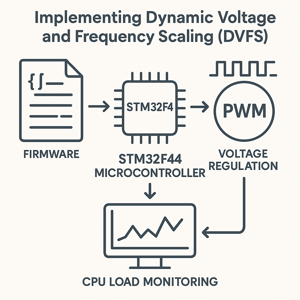
Implementing Dynamic Voltage and Frequency Scaling (DVFS) Firmware for an STM32F4 Microcontroller
Dynamic Voltage and Frequency Scaling sounds fancy, but the idea is straightforward: when your MCU isn't working hard, drop the clock speed and supply voltage to save power. When load spikes, ramp them back up. This is the same technique your laptop uses all the time—and it works just as well on an STM32F4.
The trick on a microcontroller is that you typically don't have an integrated voltage regulator you can control programmatically. So you'll use a PWM output to drive an external voltage regulator, effectively giving your firmware control over its own supply voltage. Pair that with runtime CPU load monitoring, and you've got a basic DVFS system.
Prerequisites
- Solid understanding of STM32 peripheral configuration (timers, GPIO, clocks)
- Experience with STM32CubeIDE (v1.16+)
- Familiarity with PWM and ADC concepts
- An STM32F4 development board
- External voltage regulation components
Parts/Tools
- STM32F4 development board (e.g., Nucleo-F446RE or Discovery)
- Adjustable voltage regulator with enable/feedback pin (e.g., LM2596 module)
- Multimeter for verifying output voltage
- STM32CubeIDE v1.16+
- ST-Link debugger (often built into Nucleo boards)
Steps
- Set Up the Development Environment
- Grab STM32CubeIDE v1.16+ from the STMicroelectronics website if you don't already have it.
- Create a new STM32 project, selecting your specific F4 variant. The CubeMX integration will auto-populate the pin map.
- Make sure you've got the latest STM32F4 HAL firmware pack installed—older packs sometimes have clock configuration bugs that'll drive you crazy later.
- Configure PWM for Voltage Regulation
- In the CubeMX pinout view, assign a timer channel to PWM Generation. TIM3 Channel 1 on PA6 works well for this.
- Set your PWM frequency high enough that your voltage regulator's input filter smooths it to a clean DC level. For an LM2596, something in the 10–20 kHz range works. Too low and you'll see ripple; too high and the regulator's feedback loop might not track properly.
- Generate the initialization code. CubeMX will create the
MX_TIMx_Init()function for you. - Watch out: after code generation, you still need to call
HAL_TIM_PWM_Start()manually in your main code. CubeMX generates the config but doesn't start the peripheral.
- Implement CPU Load Monitoring
- The most practical approach on STM32F4 is using the DWT (Data Watchpoint and Trace) cycle counter alongside a periodic SysTick check. This gives you accurate cycle counting without burning a timer.
- In your SysTick handler, periodically calculate what percentage of time the CPU spent in idle vs. active work:
volatile uint32_t cpuLoad = 0;

void SysTick_Handler(void) {
    HAL_IncTick();
    static uint32_t tickCount = 0;
    tickCount++;

    if (tickCount >= MONITOR_INTERVAL) {
        cpuLoad = calculateCpuLoad();
        tickCount = 0;
    }
}
Tip: A simple way to estimate load is to increment a counter in your idle loop and compare it against a known baseline (the max count when the CPU is doing nothing). The ratio tells you how busy the CPU is. It's not perfectly precise, but it's good enough for DVFS decisions.
- Adjust Voltage and Frequency Based on Load
- Define your scaling thresholds. Two or three levels is usually plenty for embedded work—don't overcomplicate this:
- Implement the scaling function. The key here is to adjust voltage before increasing frequency (upscaling) and adjust frequency before decreasing voltage (downscaling). Getting this order wrong can cause brownout resets:
#define LOW_LOAD_THRESHOLD 30 // percent #define HIGH_LOAD_THRESHOLD 70 // percent #define LOW_FREQUENCY 84000000 // 84 MHz #define HIGH_FREQUENCY 168000000 // 168 MHz #define MIN_DUTY_CYCLE 40 // percent #define MAX_DUTY_CYCLE 90 // percentvoid adjustVoltageAndFrequency(uint32_t load) { if (load < LOW_LOAD_THRESHOLD) { // Downscaling: reduce frequency first, then voltage setCpuFrequency(LOW_FREQUENCY); setPwmDutyCycle(MIN_DUTY_CYCLE); } else if (load > HIGH_LOAD_THRESHOLD) { // Upscaling: increase voltage first, then frequency setPwmDutyCycle(MAX_DUTY_CYCLE); HAL_Delay(5); // let voltage stabilize setCpuFrequency(HIGH_FREQUENCY); } }That
HAL_Delay(5)matters. The voltage regulator needs time to settle before you crank up the clock. Without it, you'll get intermittent hard faults that are almost impossible to reproduce in the debugger. - Test the DVFS Implementation
- Flash the firmware via ST-Link.
- Connect your multimeter to the voltage regulator output and watch it respond to load changes.
- Create a simple stress test—a tight loop doing floating-point math works well—and toggle it on/off to see the system scale up and down.
- Use the SWV (Serial Wire Viewer) in STM32CubeIDE to log CPU load values in real time without adding serial print overhead to your measurements.
Troubleshooting
- PWM output is flat (no signal): You probably forgot to call
HAL_TIM_PWM_Start(&htimX, TIM_CHANNEL_X)after initialization. Also check that the GPIO alternate function mapping is correct for your chosen pin. - Voltage readings are noisy or unstable: Add a low-pass RC filter between the PWM output and the regulator's feedback/enable pin. A 10k resistor + 100nF cap is a reasonable starting point. Also verify your PWM frequency isn't conflicting with the regulator's switching frequency.
- CPU load calculation doesn't change: Make sure your idle counter is actually running in the main loop's idle time and that it's declared
volatile. The compiler will optimize it away otherwise. Also verify your SysTick is firing at the expected rate—check theSystemCoreClockvalue. - Random hard faults when scaling up: You're increasing frequency before voltage has stabilized. Add a delay between the voltage increase and the frequency change, and increase it until the faults stop.
Conclusion
You've now got a working DVFS system on an STM32F4 that adjusts voltage and clock speed based on runtime load. The real-world power savings depend heavily on your application's load profile—bursty workloads benefit the most. From here, you could add more granular scaling levels, implement hysteresis to prevent rapid oscillation between states, or add current sensing (an INA219 works great for this) to measure actual power savings. Just remember: always change voltage before frequency when scaling up, and frequency before voltage when scaling down.