How to Implement DVFS Firmware on STM32F4 for Adaptive Power Management
Dynamic Voltage and Frequency Scaling on STM32F4: Adaptive Power Based on CPU Load
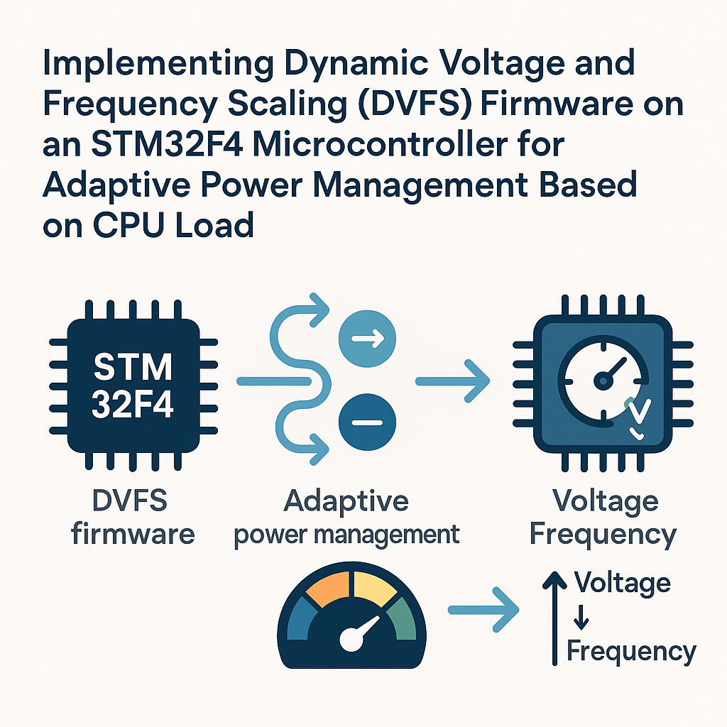
Your STM32F4 doesn't need to run full-tilt all the time. If your firmware is sitting in an idle loop 80% of the time, you're burning power for nothing. Dynamic Voltage and Frequency Scaling (DVFS) fixes that by throttling the core clock and voltage regulator scaling based on how hard the CPU is actually working.
The STM32F4's power management unit supports three voltage scaling modes (Scale 1, 2, and 3), each paired with different maximum clock frequencies. By monitoring CPU utilization and switching between these modes at runtime, you can cut power consumption significantly — especially in battery-powered or energy-harvesting designs.
Prerequisites
- Comfortable with C and STM32 HAL programming
- Working knowledge of the STM32 clock tree and RCC peripheral
- STM32F4 development board (Discovery, Nucleo-F446RE, etc.)
- STM32CubeIDE v1.16+ installed
- A multimeter or power analyzer if you want to verify real power savings
Parts and Tools
- STM32F4 dev board
- ST-Link or JTAG/SWD debugger (often built into Nucleo and Discovery boards)
- USB cable for programming and serial debug
- Optional: USB-to-UART adapter for printf-style debugging
- Optional: Multimeter or current probe to measure power draw at each scaling level
Steps
-
Set Up the Project in STM32CubeIDE
Open STM32CubeIDE and create a new STM32 project targeting your specific F4 chip. STM32CubeIDE bundles CubeMX directly into the project setup flow now, so you don't need to run CubeMX separately — just use the .ioc file that's generated with your project.
-
Configure Clocks and Power
In the .ioc graphical editor, head to the Clock Configuration tab. Set up your PLL to target the max frequency your chip supports (168 MHz on the F407, 180 MHz on the F446, etc.). This will be your "full power" baseline.
Under System Core > PWR, make sure voltage regulator output is set to Scale 1 (the highest performance mode). Enable the SysTick timer — you'll use it for CPU load measurement.
Also enable any UART you want for debug output and generate the project code.
-
Implement the DVFS Adjustment Function
The core idea: change the HCLK prescaler and voltage scaling register based on measured CPU load. Here's a straightforward implementation:
#include "stm32f4xx_hal.h"

void DVFS_Adjust(uint32_t load_percent) {
    if (load_percent < 20) {
        /* Low load: drop to SYSCLK/4 and Scale 3 (lowest power) */
        __HAL_PWR_VOLTAGESCALING_CONFIG(PWR_REGULATOR_VOLTAGE_SCALE3);
        HAL_RCC_HCLKConfig(RCC_SYSCLK_DIV4);
    } else if (load_percent < 60) {
        /* Medium load: SYSCLK/2 and Scale 2 */
        __HAL_PWR_VOLTAGESCALING_CONFIG(PWR_REGULATOR_VOLTAGE_SCALE2);
        HAL_RCC_HCLKConfig(RCC_SYSCLK_DIV2);
    } else {
        /* High load: full speed, Scale 1 */
        __HAL_PWR_VOLTAGESCALING_CONFIG(PWR_REGULATOR_VOLTAGE_SCALE1);
        HAL_RCC_HCLKConfig(RCC_SYSCLK_DIV1);
    }
}
Watch out: you should change the voltage scale before increasing frequency, and change frequency before decreasing voltage scale. The code above works for ramping down. If you're ramping up from Scale 3 to Scale 1, reverse the order — set the voltage scale first, wait for the PWR_FLAG_VOSRDY flag, then increase the clock divider. Getting this wrong can cause a hard fault or brownout.
-
Measure CPU Load
A common approach is to track how much time the CPU spends in the idle loop versus doing real work. Use the SysTick or a dedicated timer:
static volatile uint32_t idle_ticks = 0;
static volatile uint32_t total_ticks = 0;

/* Call this from your SysTick handler every 1ms */
void CPU_Load_Tick(void) {
    total_ticks++;
}

/* Call this continuously in your idle/default loop */
void CPU_Load_IdleTick(void) {
    idle_ticks++;
}

uint32_t Get_CPULoad(void) {
    if (total_ticks == 0) return 0;
    uint32_t load = 100 - ((idle_ticks * 100) / total_ticks);
    idle_ticks = 0;
    total_ticks = 0;
    return load;
}
Then in your main loop (or a periodic timer callback), call the adjustment:
while (1) {
    uint32_t load = Get_CPULoad();
    DVFS_Adjust(load);
    HAL_Delay(1000); /* Re-evaluate every second */
    CPU_Load_IdleTick();
}
Tip: don't adjust DVFS too frequently. Clock and voltage transitions aren't free — they take a few microseconds and can disrupt time-sensitive peripherals. Once per second is a reasonable starting point.
-
Test and Verify
Build and flash the firmware. Connect a multimeter across the power supply pins (or better yet, use a current shunt and scope) to see actual current draw change as you vary the workload.
A simple way to create artificial load: toggle a GPIO in a tight loop for N milliseconds, then idle. Watch the DVFS function respond by scaling up and down.
Troubleshooting
- Hard fault when switching clocks: You're probably increasing frequency before the voltage regulator is ready. Always check PWR_FLAG_VOSRDY after changing voltage scale before bumping the clock up.
- No visible power change: Make sure you're measuring at the MCU supply pins, not the USB input (the LDO on most dev boards masks small changes). Also confirm the voltage scaling register actually changed — read it back in the debugger.
- Peripherals misbehaving after clock change: UART baud rates, SPI clocks, and timer periods all derive from HCLK or APB clocks. When you change HCLK, you need to reconfigure peripheral clock dividers or accept the changed baud rate. This is the biggest real-world gotcha with DVFS.
- CPU load reads 0% or 100% constantly: Double-check that your idle tick function is actually being called in the right place. It needs to run only when the CPU has nothing else to do.
Where to Go From Here
This basic DVFS approach already makes a real difference in battery life. For production firmware, consider adding hysteresis to your threshold logic so the system doesn't bounce between modes rapidly. You can also combine DVFS with STM32 low-power modes (Sleep, Stop, Standby) for even deeper power savings during truly idle periods. If you're running FreeRTOS, the idle hook is a natural place to drop into a lower power state — and the tick-based CPU load measurement maps cleanly onto the RTOS idle task.