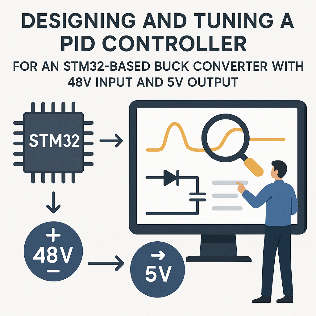
How to Design and Tune a PID Controller for STM32 Buck Converter
PID Control for Buck Converters: Getting Stable Output Voltage
A buck converter without proper closed-loop control is just a fancy way to make unstable voltage. The moment your load changes—a motor spins up, an LED strip turns on—the output voltage sags or spikes. PID control fixes this by continuously adjusting the PWM duty cycle based on the difference between your target voltage and what the ADC actually measures.
This guide walks through building and tuning a PID controller on an STM32 for a 48V-to-5V buck converter. The principles apply to any DC-DC conversion ratio, but 48V input deserves extra respect—wiring mistakes at that voltage let out the magic smoke fast.
Prerequisites
- Understanding of buck converter topology (inductor, MOSFET, diode, capacitor, and how they work together).
- Basic grasp of PID control theory—what proportional, integral, and derivative terms actually do.
- Comfortable writing C for STM32 using the HAL library.
- Experience reading an oscilloscope. You'll live on it during tuning.
- Familiarity with STM32CubeIDE v1.16+ and CubeMX peripheral configuration.
Parts/Tools
- STM32F4 or STM32G4 series development board. The G4 is a particularly good fit since it has high-resolution timers (HRTIM) designed for power conversion.
- Buck converter power stage—either a custom board or an evaluation module rated for 48V input, 5V output.
- 48V DC power supply (bench supply with current limiting is safest for development).
- Power resistors or electronic load for testing under varying conditions.
- STM32CubeIDE v1.16+.
- Oscilloscope (at least 2 channels—one for output voltage, one for PWM).
- Multimeter for DC measurements.
Steps
- Set Up the Hardware
- Connect the buck converter's control input (gate driver signal) to a PWM-capable pin on your STM32. Double-check the logic level—many gate drivers want 5V or 12V logic, not 3.3V. You may need a level shifter.
- Wire the buck converter's output through a voltage divider to an ADC input on the STM32. The divider must bring 5V (or your max expected output) down to the 0–3.3V ADC range. A 10k/10k divider gives you a 2.5V reading at 5V output—plenty of headroom.
- Connect your 48V supply to the input. Use a current-limited bench supply set to maybe 0.5A initially. When something goes wrong (and it will during development), current limiting prevents fire.
- Attach a load resistor to the output. Start with a light load—say a 100Ω resistor for 50mA at 5V.
- Verify all connections with a multimeter before powering anything up. Measure the input supply, check for shorts between power rails and ground.
- Configure Peripherals in STM32CubeIDE
- Create a new project targeting your STM32 MCU. Open the .ioc file in CubeMX.
- Configure a timer (TIM1 or HRTIM on G4) for PWM output. Set the frequency to match your buck converter's switching frequency—typically 100kHz to 500kHz for a 48V converter. Calculate prescaler and ARR values accordingly.
- Configure an ADC channel for reading the output voltage. Enable DMA or use interrupt-driven conversion for consistent sampling. Set the ADC to trigger from the timer so readings are synchronized with the PWM cycle.
- Set up a second timer (TIM2 or TIM6) for the PID control loop. A 10kHz loop rate (100µs period) is a reasonable starting point for a 100kHz+ switching converter.
- Generate the code and verify it compiles clean.
- Implement the PID Algorithm
- Define your PID structure. Keeping state in a struct makes it clean and reusable:
typedef struct { float Kp; float Ki; float Kd; float integral; float prev_error; float output_min; float output_max; } PID_t; void PID_Init(PID_t *pid, float kp, float ki, float kd, float out_min, float out_max) { pid->Kp = kp; pid->Ki = ki; pid->Kd = kd; pid->integral = 0.0f; pid->prev_error = 0.0f; pid->output_min = out_min; pid->output_max = out_max; } - Implement the PID update function. Anti-windup clamping on the integral term is not optional—without it, the integral winds up during saturation and causes massive overshoot when the system recovers:
float PID_Update(PID_t *pid, float setpoint, float measured, float dt) { float error = setpoint - measured; /* Proportional */ float p_term = pid->Kp * error; /* Integral with anti-windup */ pid->integral += error * dt; float i_term = pid->Ki * pid->integral; /* Derivative (on error, consider on measurement to avoid derivative kick) */ float d_term = pid->Kd * (error - pid->prev_error) / dt; pid->prev_error = error; float output = p_term + i_term + d_term; /* Clamp output */ if (output > pid->output_max) { output = pid->output_max; pid->integral -= error * dt; /* anti-windup */ } else if (output < pid->output_min) { output = pid->output_min; pid->integral -= error * dt; /* anti-windup */ } return output; } - Call
PID_Updatefrom your control loop timer ISR. Convert the ADC reading to voltage (accounting for the voltage divider ratio), run it through the PID, and set the PWM duty cycle:void TIM6_DAC_IRQHandler(void) { HAL_TIM_IRQHandler(&htim6); float measured_v = ReadOutputVoltage(); /* ADC + divider math */ float duty = PID_Update(&buck_pid, 5.0f, measured_v, 0.0001f); __HAL_TIM_SET_COMPARE(&htim1, TIM_CHANNEL_1, (uint32_t)(duty * htim1.Init.Period)); }
- Define your PID structure. Keeping state in a struct makes it clean and reusable:
- Tune the PID Parameters
- Start with only proportional gain. Set Ki=0, Kd=0, and Kp to something small like 0.5. Power up and watch the output on your scope. You should see the output respond to the setpoint but probably settle below 5V (that's steady-state error—expected without the integral term).
- Increase Kp gradually until the output starts to ring or oscillate. Back off by about 30–40%. This is your working proportional gain.
- Now add integral gain. Start Ki very small (like 0.1). The integral term eliminates steady-state error—your output should now hit exactly 5V. If it overshoots and rings, Ki is too high.
- Add derivative gain last. Kd damps oscillations and improves transient response. Start around 0.01 and work up. Too much Kd amplifies noise from the ADC, making the output jittery.
- Tip: the Ziegler-Nichols method works here. Increase Kp until you get sustained oscillation, note that value (Ku) and the oscillation period (Tu), then calculate Kp=0.6*Ku, Ki=1.2*Ku/Tu, Kd=0.075*Ku*Tu. Use these as a starting point, then fine-tune by hand.
- Test Under Load Transients
- With PID tuned at a light load, suddenly switch to a heavy load (or use an electronic load with transient mode). Watch the output voltage dip and recovery on the oscilloscope.
- Target specs: voltage dip under 200mV, recovery within 1–2ms. If the dip is too deep, increase Kp. If recovery is slow, increase Ki. If it rings excessively, increase Kd or reduce Ki.
- Test the reverse: remove load suddenly. Output voltage will spike—same tuning tradeoffs apply.
- Sweep across your expected load range and verify stability at every point. A PID tuned at 1A might oscillate at 0.1A or 5A.
Troubleshooting
- Output voltage oscillates continuously:
- Kp is too high. Reduce it. If oscillation persists even at very low Kp, check your feedback path—the ADC sampling might be introducing delay, or your voltage divider might have too much capacitance.
- Check your control loop timing. If the ISR takes longer than the timer period, you're skipping updates and the loop effectively runs at a lower, unpredictable rate.
- Output voltage is correct but noisy/jittery:
- ADC noise is getting amplified by the derivative term. Add a simple low-pass filter on the ADC reading (exponential moving average works well). Or reduce Kd.
- Check your ADC reference voltage—noisy VREF means noisy readings regardless of your software.
- Output drifts slowly over time:
- Your ADC might have temperature-dependent offset. Recalibrate or add periodic auto-calibration.
- Check the voltage divider resistor values—cheap resistors drift with temperature.
- System doesn't respond at all:
- Verify PWM output with an oscilloscope directly at the MCU pin. If the PWM is there, the problem is in your power stage or gate driver.
- Make sure your output_min and output_max bounds in the PID are reasonable. A min of 0.0 and max of 1.0 (representing 0–100% duty cycle) is typical.
Summary
PID tuning for a buck converter is more art than science once you get past the initial calculations. Start with P-only, get close, add I to eliminate the offset, add D to tame the transients. Anti-windup on the integral term is non-negotiable for power conversion—without it, startup and load transients cause wild overshoots that can damage downstream components. Always tune with a scope connected, always test across your full load range, and if you're using a 48V input, always use a current-limited supply during development. Your components and your eyebrows will thank you.