How to Configure STM32 EXTI for Button Presses with Hardware Debouncing
Why Hardware Debouncing?
Every mechanical button bounces. You press it once, but the electrical contact chatters open and closed for a few milliseconds, and your interrupt fires five times instead of one. Software debouncing works, but it burns CPU cycles and adds complexity to your ISR. A simple RC filter on the hardware side eliminates the noise before it ever reaches your GPIO pin, keeping your interrupt handler clean and predictable.
This guide walks through setting up an STM32 EXTI (External Interrupt) with a hardware debounce circuit using a pull-up resistor and capacitor. We'll configure everything in STM32CubeIDE (v1.16+) and write a minimal interrupt handler.
Prerequisites
- Basic microcontroller programming experience
- Familiarity with STM32CubeIDE and the HAL library
- An STM32 development board (Nucleo, Discovery, or custom — any STM32 family works)
Parts and Tools
- STM32 development board
- Momentary push button
- 10kΩ pull-up resistor
- 10µF ceramic or electrolytic capacitor (100nF also works for faster response — more on that below)
- Jumper wires and breadboard
- STM32CubeIDE v1.16+
Steps
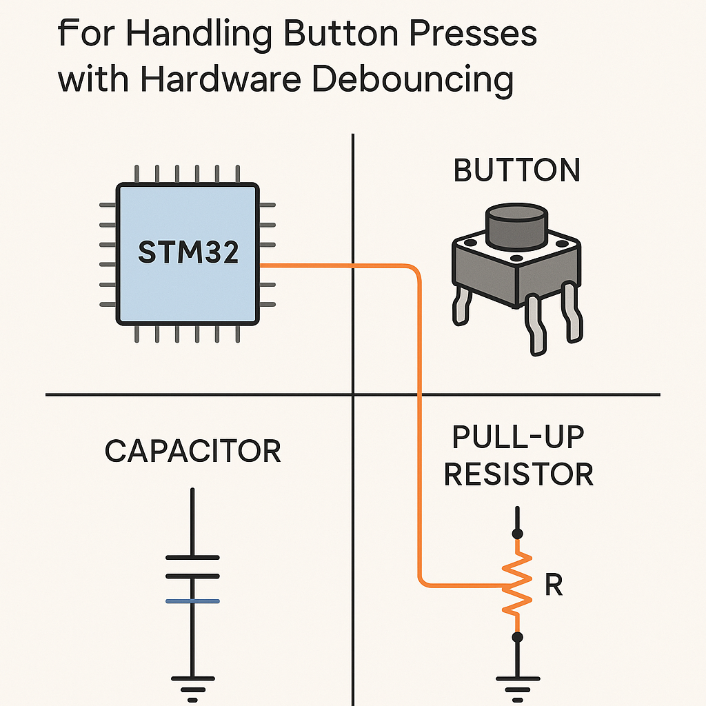
- Wire Up the Debounce Circuit
The idea is simple: the capacitor smooths out the voltage transitions caused by contact bounce. The pull-up resistor holds the line high when the button is open, and the RC time constant determines how aggressively the filtering works.
- Connect one side of the push button to GND.
- Connect the other side to your chosen GPIO pin (say PA0).
- Place the 10kΩ resistor between the GPIO pin and 3.3V (VCC). This is your pull-up.
- Place the capacitor between the GPIO pin and GND, in parallel with the button.
    VCC (3.3V) ---- [10kΩ] ---- GPIO_PIN ---- [Button] ---- GND
                                    |
                                 [10µF]
                                    |
                                   GND
Watch out: a 10µF cap gives you a time constant of about 100ms (R × C = 10k × 10µF = 0.1s). That's great for debouncing but introduces noticeable lag if you're doing rapid button presses. For a snappier feel, try 100nF to 1µF. I usually go with 100nF for UI buttons and 10µF only when the environment is electrically noisy.
- Configure the GPIO and EXTI in STM32CubeIDE
- Open STM32CubeIDE and create a new STM32 project for your board.
- In the Pinout & Configuration view, click your GPIO pin (e.g., PA0) and set it to GPIO_EXTI0.
- In the GPIO configuration panel, set the mode to "External Interrupt Mode with Falling Edge Trigger Detection." Falling edge because the pin goes from HIGH (pulled up) to LOW when you press the button.
- Under System Core > NVIC, enable the EXTI line interrupt for your pin (e.g., "EXTI line0 interrupt").
- Generate the code.
Tip: you can skip the external pull-up resistor and use the internal pull-up by setting the GPIO pull mode to "Pull-up" in CubeMX. But internal pull-ups are typically 30–50kΩ on STM32, which changes your RC time constant. For reliable hardware debouncing, an external 10kΩ gives you more predictable results.
- Write the Interrupt Handler
STM32CubeIDE generates the IRQ handler scaffolding for you. Open your
stm32fxxx_it.c(orstm32g0xx_it.c, etc., depending on your chip family). The HAL callback is the cleanest place to put your logic:void HAL_GPIO_EXTI_Callback(uint16_t GPIO_Pin) { if (GPIO_Pin == GPIO_PIN_0) { // Your button press logic here HAL_GPIO_TogglePin(GPIOA, GPIO_PIN_5); // Toggle an LED, for example } }Don't put heavy work inside the callback. Set a flag, toggle a pin, or push to a queue if you're using FreeRTOS (v11.x). Keep the ISR fast.
The auto-generated
EXTI0_IRQHandlerin the IT file already callsHAL_GPIO_EXTI_IRQHandler(GPIO_PIN_0), which clears the pending bit and calls your callback. You generally don't need to touch the IRQ handler directly unless you're doing something custom. - Build and Flash
- Build the project (Ctrl+B) and check for errors.
- Connect your board via ST-Link.
- Flash using Run > Debug or Run > Run (the green play button).
- Test It
- Press the button and watch your LED toggle (or check serial output, depending on what you put in the callback).
- Try rapid presses. You should get one clean trigger per press with no double-fires.
- If you still see occasional double triggers, increase the capacitor value slightly or add a small software cooldown (e.g., ignore interrupts within 50ms of the last one) as a belt-and-suspenders approach.
Troubleshooting
- Button press not detected at all: Double-check your wiring. Make sure the pull-up resistor goes to 3.3V, not 5V (most STM32 GPIOs are not 5V-tolerant). Verify the EXTI line is enabled in NVIC.
- Still getting false triggers: The capacitor value may be too small, or there's noise coupling in from nearby traces. Try increasing the cap or shortening your wires. Also confirm you're triggering on the correct edge (falling for active-low buttons).
- Interrupt fires once and then stops: Make sure the pending bit is being cleared. If you're using the HAL callback approach, this is handled automatically. If you wrote a custom IRQ handler, you need to call
__HAL_GPIO_EXTI_CLEAR_IT(GPIO_PIN_0)yourself. - Sluggish response: Your RC time constant is too large. Reduce the capacitor value. 100nF with a 10kΩ resistor gives a 1ms time constant, which is usually plenty for debouncing.
Wrapping Up
Hardware debouncing with an RC filter is one of those old-school techniques that still works perfectly. It offloads the problem from software entirely, so your EXTI handler stays simple and your firmware stays clean. Start with a 100nF cap and a 10kΩ resistor, test it, and adjust from there. If you're building a product, I'd always pair hardware debouncing with a minimal software guard — real-world environments have a way of surprising you.