Blinky: How to Make an Arduino Light Up an LED
The infamous “blinky” program is one that has stood the test of time, and is meant to validate hardware, software, and serve as a basis for all future development. Almost all embedded developers have started with this simple blink program, which aims to make an LED light up using hardware. This project serves as a start to your embedded journey.
Get Started:
Looking to get started with embedded systems? We recommend some of the essential tools and boards that every engineer and hobbyist should have on their bench.
Arduino Uno – https://amzn.to/3JkjAXi
Must have Elegoo Starter Kit – https://amzn.to/3JmaKbf
The Elegoo Uno works exactly like the Arduino Uno, same framework and everything! Only, it is cheaper.
Another Option – https://amzn.to/45jl6Bq
1. Overview & Goals
This project demonstrates how to control an LED with an Arduino Uno using a simple digital output.
You’ll learn:
- How to connect an LED safely to an Arduino GPIO pin.
- How to write and upload Arduino code to blink an LED.
- The basic principles of current limiting and digital I/O.
This is the foundation for all more advanced Arduino-based control projects.
2. System Architecture
Block Diagram:
[PC + Arduino IDE] –> USB Serial –> [Arduino Uno] –> GPIO Pin –> [LED + Resistor] –> GND
- Arduino Uno acts as the microcontroller.
- GPIO pin outputs HIGH (5 V) or LOW (0 V) to control LED.
- Resistor limits current to safe levels.
- USB provides programming interface and power.
3. Bill of Materials (BOM)
| Item | Qty | Part Number / Spec | Vendor Example Link |
| Arduino Uno R3 | 1 | ATmega328P-based | Arduino Store |
| LED (5 mm, red) | 1 | Vf ~ 2 V, If ~ 20 mA | Adafruit |
| Resistor | 1 | 220 Ω ±5%, ¼ W | Digi-Key |
| Breadboard | 1 | Standard 400 tie-points | Amazon / Adafruit |
| Jumper Wires (Male–Male) | 3 | 20–22 AWG | Amazon / Adafruit |
| USB Cable | 1 | USB Type-B | Included with Arduino |
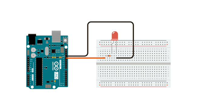
4. Hardware Setup
Electrical Schematic:
+5V (Arduino GPIO pin 13)
│
│
[220Ω]
│
[ LED ]
│
GND
Pin Mapping Table:
| Arduino Pin | Connection | Notes |
| D13 | Resistor → LED Anode (+) | Built-in LED also connected here |
| GND | LED Cathode (–) | Common ground |
Wiring Steps:
- Place the LED on the breadboard. Identify the anode (long lead, +) and cathode (short lead, –).
- Connect the anode to one end of the 220 Ω resistor.
- Connect the other end of the resistor to digital pin 13 on the Arduino.
- Connect the LED cathode to Arduino GND.
5. Firmware / Software Bring-Up
5.1 Install Arduino IDE
- Download from https://www.arduino.cc/en/software
- Install drivers if prompted.
5.2 Write the Program
Complete Arduino Code:
// Arduino LED Blink Example

// Blinks LED on pin 13 at 1 Hz

#define LED_PIN 13  // GPIO pin connected to LED

void setup() {

  pinMode(LED_PIN, OUTPUT); // Set pin as output

}

void loop() {

  digitalWrite(LED_PIN, HIGH); // Turn LED on

  delay(500);                  // Wait 500 ms

  digitalWrite(LED_PIN, LOW);  // Turn LED off

  delay(500);                  // Wait 500 ms

}
5.3 Upload to Arduino
- Connect Arduino via USB.
- In Arduino IDE:
- Select Tools → Board → Arduino Uno.
- Select Tools → Port for your device.
- Select Tools → Board → Arduino Uno.
- Click Upload (right arrow icon).
6. Integration Process
- With the wiring done and code uploaded, the Arduino will power the LED directly from GPIO pin 13.
- The LED will blink on and off every 0.5 seconds.
Troubleshooting:
- LED not lighting: Check polarity of LED and resistor connections.
- LED very dim: Verify resistor value is not too high (use 220 Ω).
- Compile errors: Ensure correct board is selected in Arduino IDE.
7. End-to-End Testing
- Expected behavior: LED turns on for 0.5 seconds, off for 0.5 seconds, repeatedly.
- Use the built-in LED on pin 13 as a secondary check—if it blinks, the code works even if your external LED wiring is wrong.
8. Performance & Reliability Notes
- Pin 13 has a built-in LED and resistor, but still use an external resistor for your added LED to avoid overcurrent.
- Do not draw more than 40 mA from a single GPIO pin—standard LED with 220 Ω is safe (~14 mA).
9. Next Steps & Extensions
- Control multiple LEDs by assigning different pins.
- Use analogWrite() for brightness control (PWM).
- Trigger LED using a button press.
- Replace LED with a relay or transistor to control larger loads.